Distributed Vision-Based Target Tracking Control Using Multiple Mobile Robots
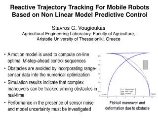
Distributed Vision-Based Target Tracking Control Using Multiple Mobile Robots. Department of Electrical and Computer Engineering Bradley University 5/3/2017. Anthony Le and Ryan Clue Advisors: Dr. Jing Wang and Dr. In Soo Ahn. Outline. Introduction Overview of QBot2 Control Design

Distributed Vision-Based Target Tracking Control Using Multiple Mobile Robots
E N D
Presentation Transcript
Distributed Vision-Based Target Tracking Control Using Multiple Mobile Robots Department of Electrical and Computer Engineering Bradley University 5/3/2017 Anthony Le and Ryan Clue Advisors: Dr. Jing Wang and Dr. In Soo Ahn
Outline • Introduction • Overview of QBot2 • Control Design • Target Identification • Kinematics • Event-Based System Control • Experimental Results • Conclusions
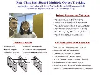
Introduction • Coordination control of multiple robots • Military and civilian applications • Environmental monitoring, threat/obstacle avoidance, search & rescue
Motivation • In the study of distributed control, one of the fundamental problems is how to make a group of robots maintain certain geometric formation pattern while tracking a target. • Local sensing information exchange among robots is the key in the design of distributed control.
Motivation • Vision sensors have been used in the localization, navigation, and control of the individual robot. • The use of vision sensors for distributed control of multiple robots should be studied.
Related Work • Peter Corke, Robotics, Vision and Control and MATLAB vision control toolbox. Sep 2011. • 2016 Senior Project: G. Bock, R. Hendrickson, J. Lamkin, B. Dhall, J. Wang, and I. S. Ahn, Cooperative Control of Heterogeneous Mobile Robots Network • Franchi, Stegagno, and Oriolo, Decentralized multi-robot encirclement of a 3D target with guaranteed collision avoidance. Feb 2016.
Objective • Design a distributed vision-based target tracking control algorithm for multiple mobile robots • To achieve the above objective, the research tasks include: • Target identification based on RGB image • Target tracking algorithm based on robot model linearization • Design leader-follower formation control algorithm • Coordinate target identification module and target control module using Stateflow
Robot Platform Maximum Velocity : 0.7 m/s.
QBot2 Software • The target computer is connected wirelessly with the host computer on which the SIMULINK model is running. • The control algorithms are developed in MATLAB/SIMULINK with QUARC on the host computer. • The control models are cross-compiled and downloaded to the target computer.
Matlab Interface: Initialization Blocks • HIL Initialization • Targets a specific Hardware-in-the-Loop(HIL) board type • Allows cross-compilation of Matlab code for the deployment platform • Kinect Initialization • Required to use Kinect sensors • Outputs current state of the associated Kinect device
Matlab Interface: Image Retrieval • Kinect Get Image • Acquires either RGB or IR image • Storesimage in Qbot2’s memory • Kinect Get Depth • Provides image of blobs with associated depth values • Utilizes Kinect’s capability to process IR image • Output values represent Cartesian distance in millimeters • Output type is 2D array of uint16
QUARC Environment Setup • Ad-hoc setting for windows 10 • Set Fixed-step size (fundamental sample time) located in Quarc\Options\Solver • This affects how frequently the Quarc interface samples the Matlab model for use by the DuoVero computer • The computer can only reliably respond to the Quarc interface at 30Hz or less (default value is 1000Hz) due to image processing. • In our project, the fundamental sample time is set to 0.1 seconds. netsh wlan set profileparameter MY_SSID connectiontype=ibss connectionmode=manual netsh wlan connect MY_SSID
Control Design • Target Identification
Target Identification • RGB image and depth image are acquired via Get Image/Depth for target/robot identification. • Image thresholding and blob detection algorithms are used in image processing.
Target Identification • Image Thresholding • Isolate sections of an image by eliminating portions of the image whose values (RGB or IR) do not fall within a particular set of constraints • Simplest method of image processing for RGB images • Blob Detection • Accuracy entirely dependent on thresholding result
Alternative Design Advantages of Color Thresholding • Low processor resource requirements Disadvantages of Color Thresholding • White balancing • Differences in lighting will drastically affect results (including outside weather) • Unable to threshold entire target without also matching large portions of the surrounding environment
Alternative Design All color values are between 0 (darkest) and 255 (lightest) Actual threshold values are +20 and -20 the numbers shown on this chart
Circle Hough Transform If down-sampling is used to improve speed, a blur filter will be applied before attempting to detect edges.
Circle Hough Transform – Canny Edge Detection Generalized Hough Transform requires “thin” edges before applying the transform
Circle Hough Transform - Accumulator Transform Radius = 53 pixels Circumference = (Radius * 4) + 2 = 214 pixels Max = 110 pixels @ x=290, y=291
Shape Detection Results = (Max / Circumference) %
Design of Control Modules • Depending on whether the robot is following a target or leader robots, two separate control modules are used • Both modules use X-Y values from the converted image of the image processing module.
Control Design • Kinematic Controls
Target Encirclement Control • The linearized model is further transformed into cylindrical coordinates for encirclement control design. • , , • Encirclement control laws are given by • where kr : proportional gain, : encirclement radius , • : distance from robot to target
Target Encirclement Control • The inverse of the Jacobian matrix is used to determine and where
Target Encirclement Control • and are then converted to and • and are converted to and
Leader-Follower Control • Leader-follower control module is used for distributed multi-robot coordination • Image processing is used to localize the leader robot coordinates () in the vision sensor range • The following leader-follower control laws are implemented where =0.2 and = 0.5. Limits for angular and forward velocity are set to 0.2 m/s
Control Design • Event-based System Control
Event-based System Control • • Stateflow control is designed to coordinate control modules enabling/disabling Simulink blocks Stages • Step 1: Search for encirclement target or leader robot. If target is not in view, rotate 15° CCW and repeat this step. Otherwise continue to next stage. • Step 2: Switch to encirclement or leader-follower motion controls. If target is no longer in view, stop moving and return to step 1.
Event-based System Control: Encirclement Control
Event-based System Control: Leader-Follower Control
Event-based System Control: Image Processing
Event-based System Control: Control Options
Event-based System Control: Hardware-in-loop Input/Output
Event-based System Control: Complete Kinematic Model