Download
1 / 1
20 likes | 187 Vues
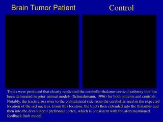
Design of a Hadamard Transform Spectral Imaging System for Brain Tumor Resection Guidance Paul Holcomb, Tasha Nalywajko, Melissa Walden Advisors: Anita Mahadevan-Jansen, Ph.D.; Steven Gebhart Vanderbilt University Department of Biomedical Engineering. -1. 1. -1. -1. 1. 1. -1. 1. X. Y.

E N D
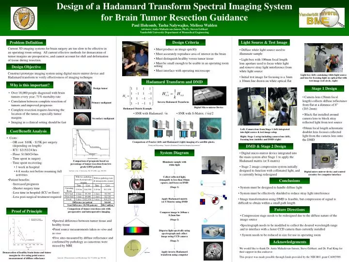
Design of a Hadamard Transform Spectral Imaging System for Brain Tumor Resection Guidance Paul Holcomb, Tasha Nalywajko, Melissa Walden Advisors: Anita Mahadevan-Jansen, Ph.D.; Steven Gebhart Vanderbilt University Department of Biomedical Engineering -1 1 -1 -1 1 1 -1 1 X Y Spectrum • SNR with Hadamard: √n • SNR with S-Matrix: (√n)/2 Problem Definition Design Criteria Light Source & Test Image Current 3D imaging systems for brain surgery are too slow to be effective in an operating room setting. All current effective methods for demarcation of tumor margins are preoperative, and cannot account for shift and deformation of tissue during resection. • Diffuse white light source used to illuminate sample • Light box with 100mm focal length lens aperture used to focus white light and remove stray light interference from white light source • Initial test image for focusing is a 3mm x 10mm line drawn on white optical flat • Must produce an image quickly • Must accurately reproduce area of interest in the brain • Must distinguish healthy versus tumor tissue • Must be small enough to be usable in an operating room setting • Must interface with operating microscope Design Objective Construct prototype imaging system using digital micro-mirror device and Hadamard transform to verify effectiveness of imaging technique. Light box (left) containing white light source and lens for focusing light on optical flat with test image (red circle, right) Hadamard Transform and DMD Why is this important? Stage 1 Design Benign tumor • Over 18,000 people diagnosed with brain tumors every year; 71% mortality rate • Correlation between complete resection of tumors and improved prognosis • Complete resection requires knowing the location of the tumor, especially tumor margins • Imaging in a clinical setting should be fast • Camera lens (28mm focal length) collects diffuse reflectance from flat at a distance of 8” (203.2mm) • Black flat installed around camera lens to block stray reflected light from test source • 50mm focal length achromatic doublet lens focuses collected light from the camera lens onto the DMD Inverse Hadamard Transform Primary malignant Digital Micro-mirror Device Hadamard Matrix Example Secondary malignant Left: Camera lens from Stage 1 (left) integrated into light source & test image setup Right: Stage 1 setup including camera lens (left), focusing lens (middle) and DMD (right) Cost/Benefit Analysis • Costs: • OR cost: $10K - $15K per surgery (depending on length) • ICU: $2152/24 hrs • Floor: $1360/24 hrs • Time spent in surgery • Time spent recovering: • 1 week in hospital • 4-8 weeks rest before resuming full activities Comparison of Fourier (left) and Hadamard (right) imaging of a satellite photo. Wuttig and Riesenburg, “Sensitive Hadamard Transform Imaging Spectrometer” DMD & Stage 2 Design System Diagram • Digital micro-mirror device integrated into the main system after Stage 1 to apply the Hadamard matrix (or S-matrix) • Stage 2 image compression system initially designed to function with collimated light, and is currently being redesigned Comparison of prognosis based on percentage of tumor resection from low grade GBM patients LaCroix et al. J. Neurosurg. Vol. 95 (2001); pp. 190-198. Illuminate sample with white light Digital micro-mirror device and control circuitry for computer interface Collect reflected light, demagnify to less than 10mm square, and focus on DMD (Stage 1) • Patient benefits: • Increased prognosis • Shorter surgery time • Less time in hospital (ICU or floor) • Less post-surgical treatment required Conclusions • System must be designed to handle diffuse light • System must be effectively shielded to reduce stray light interference • Image transformation using DMD is feasible, but compression of signal is difficult to obtain within a small path length Apply Hadamard matrix (or S Matrix) using DMD Future Directions Comparison of tumor resection costs with preoperative and intraoperative imaging Proof of Principle Compress image to 160um x 8.2mm line (Stage 2) • Compression stage needs to be redesigned due to the diffuse nature of the image source • Spectrograph needs to be modified to collect the desired wavelength range and to interface with a faster CCD camera than currently installed • System needs to be reduced in size for use in operating room • Spectral difference between tumor tissue and healthy tissue • Point source measurements taken in vitro and in vivo • Five sites measured by diffuse reflectance and confirmed by pathology as cancerous were missed by MRI Disperse light spectrally using spectrograph and collect image using CCD camera (Stage 3) Acknowledgements We would like to thank Dr. Anita Mahadevan-Jansen, Steve Gebhart, and Dr. Paul King for their support in this endeavor. This project was made possible through funds provided by the NIH R01 grant CA085989. Apply inverse Hadamard transform using computer Demarcation of healthy brain tissue and tumor margins in vivo using point source measurement of diffuse reflectance Lin et al. J Photochemistry and Photobiology, Vol. 73 (2001); pp. 396-402.