Steam turbines
280 likes | 454 Vues
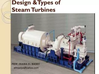
Steam turbines. The first known turbine of this type is attributed to Hero of Alexandria about the first or second century B.C. A reaction turbine built on the principle of Hero’s was demonstrated in 1883 by Gustaf de Laval, one of the most prominent poineers of steam turbine.

Steam turbines
E N D
Presentation Transcript
Steam turbines • The first known turbine of this type is attributed to Hero of Alexandria about the first or second century B.C. • A reaction turbine built on the principle of Hero’s was demonstrated in 1883 by Gustaf de Laval, one of the most prominent poineers of steam turbine. the radial tubes, which are in connection with the vertical supply tube, are free to rotate.
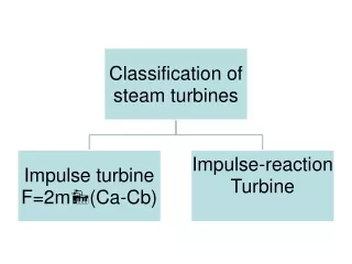
Impulse steam turbines • The steam supplied to a single wheel impulse turbine expands completely in the nozzles and leaves with a high absolute velocity, denoted by Cai. The steam is delivered to the wheel at an angle i. • Cb is the blade velocity • Cr velocity of steam relative to the blade. ri and re : relative velocities at inlet and outlet • i blade angle at inlet • e blade angle at exit
If the blade is symmetrical then i=e • re =k.ri , k is blade velocity factor • Tangential velocity of the steam relative to the blade at inlet is given by AE=ri cos i At exit: AD = -re cos e Therefore, Change of velocity in tangential direction = -re cos e- - ri cos I
So that the tangential force= -m(re cos e- + ri cos I) The reaction to this force provides the driving thrust on the wheel, i.e. the driving force on the wheel= m(re cos e- + ri cos I) But (re cos e- + ri cos I) = AD+AE=DE=w Where w is the change in velocity of whirl driving foece on the wheel =mw
The rate at which work is done on the wheel is given by the product of the driving force and the blade velocity. therefore: power output = m.w.b The axial component of the force, m.CF, is the axial thrust on the wheel, which must be taken up by the bearings in which the shaft is mounted. CF = fi – fe = f Axial thrust = m.f
The enthalpy of steam entering the nozzle is ho, and at the nozzle exit is hi. Then the maximum velocity of steam impinging on the blades is given by: • ai = {2(ho – hi)} m/s • The energy supplied to the blades is the kinetic energy of the jet, ai2/2, and the blade velocity or diagram efficiency is defined by
d = wb.(2/ai2) = 2wb/ai2 • For purpose of analysis w can be expressed as w= re cos e + ri cos I Also, if the blade velocity coefficient, k=1 (i.e. re = ri ) and if the blades are symmetrical (i.e e = i), then we have w = 2.ri cosi , But ri.cosi = ai cos i - b Hence, w = 2(ai cos i – b)
The rate of doing work per kg/s = 2(ai cos i – b)b i.e. diagram efficiency Where b/ai is called blade speed ratio
Example. 1 The velocity of steam leaving the nozzles of an impulse turbine is 900 m/s and the nozzle angle is 20. The blade velocity is 300 m/s and the blade velocity coefficient is 0.7. calculate for a mass flow of 1 kg/s, and symmetrical blading: a- the blade inlet angle b- the driving force on the wheel. c- the axial thrust d- the diagram power e- the diagram efficiency
Solution. The velocity can be drawn to scale and the angle can found directly from the velocity diagram, but the angle will be found by an analytical method to illustrate the procedure. Applying the cosine rule ri2 = ai2 +b2 – 2.b.ai cos i = 9002 + 3002 – 2*300*900 cos 20 ri = 625.5 m/s
Using the sine rule in traingle OAB ai/sin OAB = ri / sin i Also sin OAB = sin(180 - i)=sin I i.e. sin i = ai.sini / ri = (900*sin 20)/626.5 i.e. i=29 24’=e • re=kri =626.5*0.7=438.5 m/s AE = re cose=545.8 m/s AD = ri cos i = 381.9 m/s W = 545.8 + 381.9=927.7 m/s Driving force on the wheel=mw=1*927.7=927.7 N per kg/s
fi= ri.sin i=307.6 m/s • fe= re.sin e=215.3 • f=fi-fe=92.3 m/s • i.e axial thrust = m*f = 92.3 N per kg/s • Diagram power = mwb=278.3 kW • Diagram efficiency, d=2wb/ai2=0.687=68.7%
Optimum operating conditions from the blade velocity diagrams. So that And max. diagram = cos2i i.e Maximum efficiency rate of doing work per kg/s = 2.b2