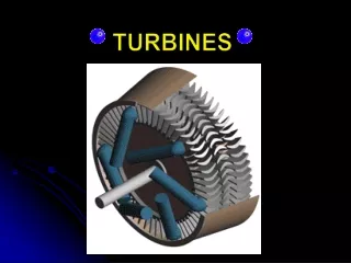
TURBINES
841 likes | 3.44k Vues
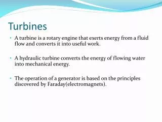
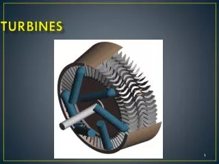
TURBINES. TURBINES. ‘Turbo Machine’ is defined as a device that extracts energy from a continuously flowing fluid by the dynamic action of one or more rotating elements .

TURBINES
E N D
Presentation Transcript
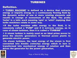
TURBINES ‘Turbo Machine’is defined as a device that extracts energy from a continuously flowing fluid by the dynamic action of one or more rotating elements . The prefix ‘turbo’ is a Latin word meaning ‘spin’ or ‘whirl’ implying that turbo machines rotate in some way.
TypesofTurbines • Steam Turbines • Gas Turbines (Combustion Turbines) • Water (Hydraulic) Turbines Srinivas School of Engineering, Mukka
Steam Turbines • A steam turbine is mainly used as an ideal prime mover in which heat energy is transformed into mechanical energy in the form of rotary motion. • A steam turbineis used in • Electric power generation in thermal power plants. • Steam power plants. • To propel the ships, submarines. In steam turbines, the heat energy of the steam is first converted into kinetic (velocity) energy which in turn is transformed into mechanical energy of rotation and then drives the generator for the power generation. Srinivas School of Engineering, Mukka
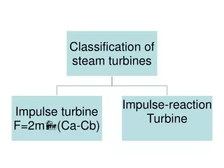
Classification of Steam Turbines Based on action of steam or type of expansion: • Impulse or velocity or De Lavalturbine • Reaction or pressure or Parson’s turbine • Combination turbine Based on number of stages: • Single stage turbine 2. Multi-stage turbine Based on type of steam flow: • Axial flow turbine 2. Radial flow turbine Srinivas School of Engineering, Mukka
Steam Turbines Srinivas School of Engineering, Mukka
Impulse turbine (De Laval Turbine) Srinivas School of Engineering, Mukka
Working Principle of Impulse Turbine • . The steam is made to fall in its pressure by expanding in a nozzle.Due to this fall in pressure, a certain amount of heat energy is converted into kinetic energy, which sets the steam to flow with a greater velocity. • The rapidly moving particles of the steam enter the rotating part of the turbine, where it undergoes a change in the direction of motion, which gives rise to a change of momentum and therefore a force. This constitutes the driving force of the turbine. Srinivas School of Engineering, Mukka
Impulse Turbines (De Laval Turbine) In this type of turbine, steam is initially expanded in a nozzlefrom high pressure to low pressure. High velocity jet of steam coming out of the nozzle is made to glide over a curved vane, called ‘Blade’.
The jet of steam gliding over the blade gets deflected very closely to surface. This causes the particles of steam to suffer a change in the direction of motion, which gives rise to a change of momentumand therefore a force, which will be centrifugalin nature. • Resultantof all these centrifugal forces acting on the entire curved surface of the blade causes it to move. Srinivas School of Engineering, Mukka
A P Q VH NOZZLE PH HIGH PRESSURE STEAM EXHAUST STEAM R Velocity Variation Pressure Variation VL C PL B TURBINE SHAFT MOVING BLADES Rotor Blades Schematic of Impulse Turbine Nozzle Pressure-Velocity diagram in Impulse Turbine Pressure-velocity changes over Impulse steam turbine Srinivas School of Engineering, Mukka
Reaction steam Turbine Principle of working - • In this type of turbine, the high pressure steam does not initially expand in the nozzle as in the case of impulse turbine, but instead directly passes onto the moving blades. Srinivas School of Engineering, Mukka
Blade shapes of reaction turbines are designed in such a way that the steam flowing between the blades will be subjected to the nozzle effect. Hence, the pressure of the steam drops continuously as it flows over the blades causing, simultaneous increase in the velocity of the steam.
Forces acting on a reaction blade • Reaction force: is due to the change in momentum relative velocity of the steam while passing over the blade passage. • Centrifugal force: is the force acting on the blade due to change in radius of steam entering and leaving the turbine. • Resultant force: is the resultant of Reaction force and Centrifugal force. Srinivas School of Engineering, Mukka
Fixed Blade Moving Blade Pressure-Velocity change in reaction turbine Srinivas School of Engineering, Mukka
Difference between Impulse & Reaction Turbines Srinivas School of Engineering, Mukka
Compounding of Impulse Turbines • As the complete expansion of steam takes in one stage (i.e., the entire pressure drop from high pressure to low pressure takes place in only one set of nozzles),the turbine rotor rotates at very high speed of about 30,000 rpm(K.E. is fully absorbed). • High speed poses number of technical difficulties like destruction of machine by the large centrifugal forces developed, increase in vibrations, quick overheating ofblades, impossibility of direct coupling to other machines, etc. • To overcome the above difficulties, the expansion of steam is performed in several stages. Srinivas School of Engineering, Mukka
Utilization of the high pressure energy of the steam by expanding it in successive stages is calledCompounding. • Methods of Compounding: • Velocity compounding (Curtis Impulse Turbine) • Pressure compounding • Pressure-velocity compounding Srinivas School of Engineering, Mukka
Velocity compounding • Comprise of nozzles and two or more rows of moving blades arranged in series. In between two rows of moving blades, one set of guide (fixed) blades are suitably arranged. • Guide (fixed) blades are fixed to casing and are stationary. Srinivas School of Engineering, Mukka
N – Nozzle M – Moving Blade F – Fixed Blade Velocity Compounding (Curtis Impulse Turbine) Srinivas School of Engineering, Mukka
Pressure compounding • Consists of two stage of nozzles followed by two rows of moving blades.
Pressure Compounding Srinivas School of Engineering, Mukka
A – Axial clearance, N – Nozzle, M – Moving Blade, F – Fixed Blade Pi and Pe – Pressure at inlet & exit, Vi and Ve- Velocity at inlet & exit Pressure-Velocity Compounding (Combined Impulse Turbine) Total pressure drop is divided into two stages & the total velocity obtained in each stage is also compounded Srinivas School of Engineering, Mukka
GAS TURBINES Srinivas School of Engineering, Mukka
GAS TURBINES • A Gas turbineuses the hot gases of combustion directly to produce the mechanical power. • Fuels used - Kerosene, coal, coal gas, bunker oil, gasoline, producer gas, etc., Classification: • Open cycle gas turbine • Closed cycle gas turbine Srinivas School of Engineering, Mukka
Applications Gas turbines are used in: • Electric power generation plants • Steel, oil and chemical industries • Aircrafts, Ship propulsion • Turbo jet and turbo-propeller engines like rockets, missiles, space ships etc., Srinivas School of Engineering, Mukka
Open cycle gas turbine: The entire flow of the working substance comes from atmosphere and is returned to the atmosphere back in each cycle. Closed cycle gas turbine: The flow of the working substance of specified mass is confined within the cyclic path. ( Air or Helium is the working substance) Srinivas School of Engineering, Mukka
Open cycle gas turbine • COMPRESSOR: • draws in air and compress it before it is fed into combustion chamber • COMBUSTOR: • fuel is added to the compressed air and burnt to produce high velocity exhaust gas • TURBINE: • extracts energy from exhaust gas Srinivas School of Engineering, Mukka
Closed Cycle Gas Turbine Srinivas School of Engineering, Mukka
WATER TURBINES Srinivas School of Engineering, Mukka
WATER (HYDRAULIC) TURBINES It is a prime mover, which converts hydro power (energy of water) into mechanical energy and further into hydro-electric power. Srinivas School of Engineering, Mukka
Classification of Water Turbines Based on action of water: • Impulse turbine – pelton wheel. • Reaction turbine – francis and kaplan. Based on name of originator: • Pelton turbine or Pelton wheel • Francis turbine • Kaplan turbine Based on head of water: • Low head turbine • Medium head turbine • High head turbine Srinivas School of Engineering, Mukka
Pelton Turbine (Pelton Wheel or Free Jet Turbine) • High head, tangential flow, horizontal shaft, impulse turbine Srinivas School of Engineering, Mukka
PELTON TURBINE Srinivas School of Engineering, Mukka
Pelton Turbine Runner Srinivas School of Engineering, Mukka
REACTION TURBINE • Only a part of the pressure energy of the water is converted into K.E. and the rest remains as pressure head. Srinivas School of Engineering, Mukka
First, the water passes to the guide vanes which guide or deflect the water to enter the blades, calledmoving blades, mounted on the turbine wheel, without shock. • The water from the guide blades are deflected on to the moving blades, where its part of the pressure energy is converted into K.E., which will be absorbed by the turbine wheel. The water leaving the moving blades will be at a low pressure. Srinivas School of Engineering, Mukka