Download
1 / 16
231 likes | 753 Vues
DIAGNOSTIC ULTRASOUND IMAGING CALIBRATION. Without reference, identify principles relating to Diagnostic Ultrasound Imaging Calibration with at least 70 percent accuracy. . DIAGNOSTIC ULTRASOUND IMAGING CALIBRATION. General Ultrasound Knowledge Other names Real-time scanners

E N D
DIAGNOSTIC ULTRASOUND IMAGING CALIBRATION • Without reference, identify principles relating to Diagnostic Ultrasound Imaging Calibration with at least 70 percent accuracy.
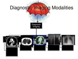
DIAGNOSTIC ULTRASOUND IMAGING CALIBRATION • General Ultrasound Knowledge • Other names • Real-time scanners • 2-D scanners • Duplex scanners • Echocardiographs • Cardiac ultrasound imagers • Vascular ultrasound imagers • Common uses • Cardiology • Diagnostic imaging • Obstetrics and gynecology • Ophthalmology • Radiology • Surgery • Vascular lab • Emergency department
DIAGNOSTIC ULTRASOUND IMAGING CALIBRATION • Scope • This procedure covers all diagnostic ultrasound scanners, including general-purpose and dedicated systems • This procedure does not cover nonimaging diagnostic ultrasound systems such as doppler blood-flow detectors and doppler fetal heart monitors • Test Equipment Required • Multipurpose phantom - comprehensively evaluate the performance of diagnostic ultrasound imaging systems with the following capabilities • Dead-zone or ring-down • Vertical and horizontal measurement calibration • Focal zone • Sensitivity • Axial and lateral resolution • Functional resolution • Grayscale and displayed dynamic range
DIAGNOSTIC ULTRASOUND IMAGING CALIBRATION • Material • The phantom should be designed with a combination of monofilament line targets and tissue-mimicking cylindrical targets of varying sizes and contrasts • The monofilament line targets should have a diameter of 0.1 mm to 0.5 mm ±5% to optimize the displayed image at frequencies typically used on general-purpose scanners • Monofilament line targets with diameters of approximately 0.5 mm should be present to optimize the displayed image at the high ultrasound frequencies typically used on small-parts scanners • Doppler flow phantom - comprehensive evaluation of ultrasound scanners that incorporate continuous-wave, pulsed-wave, or color-flow Doppler capabilities with the following capabilities: • Flow velocity • Location of flow • Directional discrimination
DIAGNOSTIC ULTRASOUND IMAGING CALIBRATION • Material • The phantom can be either the tissue-mimicking type with one or more fluid-flow channels (containing a non-degradable blood-mimicking solution with calibrated reflecting targets) or the type that incorporates a moving string target within a fluid-filled container • The string phantom provides greater accuracy for flow velocity calibration • NOTE: • To check only basic Doppler operation, it is not necessary to use the calibrated Doppler phantoms described above • A less-costly blood-flow simulator may be purchased, or one may be constructed using a fluid pump and flexible tubing submerged within a fluid-filled container • In lieu of the nondegradeable blood-mimicking solution with calibrated reflecting targets, any echogenic fluid, such as a detergent-water solution, may be used • Blood flow simulator - for checking doppler ultrasound • Ecg simulator • Leakage current meter • Ground resistance ohmeter
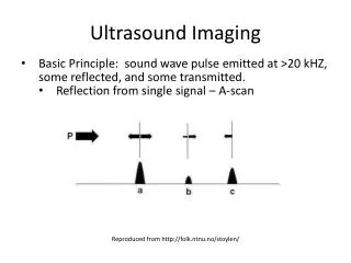
DIAGNOSTIC ULTRASOUND IMAGING CALIBRATION • Overview • Ultrasounds typically provide 2-D images of soft tissue • Scanners also provide waveforms (M-mode) • Newer scanners have 3-D capabilities • Ultrasound refers to sound waves emitted at frequencies above the level of human hearing • For diagnostic imaging, frequencies ranging from 2 to 10 MHz are typically used • Ultrasound waves are mechanical vibrations that require a medium for transmission • Echoes are produced whenever the beam encounters an interface of different acoustic impedances, such as the soft-tissue/bone interface • Transducer • Placed on the skin after an acoustic coupling gel is applied • Converts an electrical signal into ultrasonic energy that can be transmitted into tissues • Reconverts reflected signal into an electrical signal
DIAGNOSTIC ULTRASOUND IMAGING CALIBRATION • Procedure • Note: • Before beginning an inspection, carefully read this procedure and the manufacturer's instruction and service manuals • Know how to operate the equipment and the significance of each control and indicator. Also review special inspection and preventive maintenance procedures or frequencies recommended by the manufacturer • Transducer Identification and Scanner Settings for Tests with the Multipurpose Ultrasound Phantom (Record the Type, Serial #, Frequency, Settings, Power, Gain, Dynamic Range, etc.)
DIAGNOSTIC ULTRASOUND IMAGING CALIBRATION • Measurements • Dead Zone - place the transducer over the dead zone line target group. Determine the minimum distance (in mm) at which the scanner can resolve individual structures • Axial resolution - place the transducer over one of the axial resolution line target groups. Determine the minimum reflector separation (in mm) along the axis of the transducer beam required to produce separate reflections • Lateral resolution • Place the transducer over each lateral resolution line target group • Determine the minimum reflector separation (in mm) perpendicular to the sound path needed to produce discrete reflections • Because lateral resolution can vary with depth, multiple transducer locations should be used • Record the lateral resolution for each depth checked • If the transducer has adjustable transmit focus, verify its operation and perform each lateral resolution measurement in the respective focal zone, if possible
DIAGNOSTIC ULTRASOUND IMAGING CALIBRATION • Vertical Distance • Place the transducer over a vertical distance calibration line target group • Use the scanner's digital calipers and/or marker grids to determine the accuracy of linear measurements along the axis of the transducer beam at 20 mm and 100 mm measured distances • Horizontal Distance • Place the transducer over a horizontal distance calibration line target group • Use the scanner's digital calipers and/or marker grids to determine the accuracy of linear measurements perpendicular to the sound path • On images produced by flat sequenced linear-array transducers, check at 20 mm and 60 mm measured distances, using any left to right location • On images produced by sector transducers, check at 20 mm and 60 mm measured distances, but at multiple left to right positions. If the transducer has adjustable transmit focus, perform measurements within the focal zone, if possible • Doppler Calibration • If a calibrated Doppler ultrasound phantom is available, verify the accuracy of flow velocity, directional discrimination, and, if applicable, pulsed-Doppler gate positioning • Measurement parameters and display quality should not vary between inspections with the same transducer configuration, scanner settings, and technique • Operator Calibration - ensure operator calibrations are performed according to the manufacturers manuals
DIAGNOSTIC ULTRASOUND IMAGING CALIBRATION • Other Checks • Accessories • Confirm the presence and condition of accessories (e.g., transducers and coupling gel) • Verify that expiration dates have not been exceeded • A copy of the instruction manual should be readily available to the operators • Chassis/housing • Examine the exterior of the scanner for cleanliness and general physical condition • Be sure that plastic housings are intact, that all hardware is present and tight, and that there are no signs of spilled liquids or other serious abuse
DIAGNOSTIC ULTRASOUND IMAGING CALIBRATION • AC plug/receptacles • Examine the AC power plug for damage • Wiggle the blades to check for security • Shake the plug and listen for rattles • If damage is suspected, open the plug and inspect it • For receptacles mounted on the scanner - verify the presence of line power, and insert an AC plug into each and check that it is held firmly. • Line cord • Inspect the cord for signs of damage • If damaged, replace the entire cord or, if the damage is near one end, cut out the defective portion • Be sure to wire a new power cord or plug with the correct polarity • Strain reliefs • Examine the strain reliefs at both ends of the line cord • Be sure that they hold the cord securely
DIAGNOSTIC ULTRASOUND IMAGING CALIBRATION • Circuit breaker/fuse • If the scanner has a switch-type circuit breaker, check that it moves freely • If the scanner is protected by an external fuse, check its value and type against that marked on the chassis • Cables • Inspect any cables (e.g., transducer) and their strain reliefs for general condition • Carefully examine cables to detect breaks in the insulation and to ensure that they are gripped securely in the connectors at each end to prevent rotation or other strain • Verify that there are no intermittent faults by flexing electrical cables near each end and looking for erratic operation or by using an ohmmeter • Transducers • Check the surface areas of ultrasound transducers for deterioration, cracks, or dents in the membrane • Check the acoustic fluid of mechanically steered transducers; refill with the recommended fluid if air bubbles are present
DIAGNOSTIC ULTRASOUND IMAGING CALIBRATION • Controls/switches • Before changing any controls, check their positions • If any settings appear unusual (e.g., a gain control at maximum), consider the possibility of inappropriate clinical use or of incipient device failure • Record the setting of those controls that should be returned to their original positions following the inspection • Physical condition • Secure mounting, and correct motion • Check that control knobs have not slipped on their shafts • Control fixed-limit stops, alignment, as well as positive stopping • Each control and switch performs its proper function
DIAGNOSTIC ULTRASOUND IMAGING CALIBRATION • Indicators/displays • Record the reading of an hour meter, if present • During the course of the inspection, confirm the operation of all lamps, indicators, meters, gauges, and visual displays on the scanner • Be sure that all segments of a digital display function • Observe an image on the CRT display, and check its quality Also verify image quality of peripheral accessories • Audible signals (Confirm appropriate volume, as well as the operation of a volume control) • ECG - Using an ECG simulator, verify normal operation of ultrasound scanners configured for echocardiography, according to the following criteria: • Baseline - constant thickness; horizontal and no vertical drift • ECG waveform should be clearly visible, including the P wave and QRS complex • 50/60 Hz noise should not be present • Intervals between the timing marks displayed by the scanner should be consistent with the timing of the ECG simulator