Download
1 / 27
270 likes | 478 Vues
BalloonWinds Status Update. Presented By: Michael Dehring June 29, 2005. Discussion Outline. Review of Flight Schedule and Goals Program Status System changes since last meeting Engineering Hardware Update: Build and Design Progress Current Best Estimate Performance.

E N D
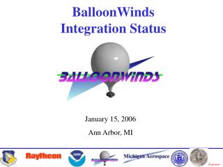
BalloonWinds Status Update Presented By: Michael Dehring June 29, 2005
Discussion Outline • Review of Flight Schedule and Goals • Program Status • System changes since last meeting • Engineering Hardware Update: Build and Design Progress • Current Best Estimate Performance
BalloonWinds Overview/Goals • Demonstrate Multi-Order Photon Recycled Fringe Imaging from a high altitude (30 km) balloon • Demonstrate technology under as many atmospheric conditions as possible; i.e. high and low clouds, high and low winds, variable boundary layer aerosol conditions, day and nighttime • Validate LIDAR models for a downward looking platform
Flight Schedule • Comments/ Notes • All balloon flights will include molecular and aerosol channel optimized interferometers • First 2 flights are intended to be concept demonstrations • Flight 1: Demonstrate the electrical, thermal, mechanical, and optical performance of the integrated instrument for nighttime flight conditions. • Flight 2: Demonstrate the ability to operate during the daytime given the additional thermal load and the increased optical background • Instrument modifications required for the final flight will be made in the 6 months leading up to the final flight.
BalloonWinds Gondola/Instrument Concept Interferometer Chamber Laser Chamber & Telescope Battery Stacks Control Electronics Chamber Telemetry Electronics Coolant Chamber Overall System Attributes • Gondola Mass: 4800 lbs • Power Requirements: 1300 W • Thermal Management: Ice Phase Change, 0°C coolant temperature • Size: 8’ h x 8’w x 12’ l • 26-28 Lithium Ion Batteries • Technologies Implemented • Dual Channel Photon Recycled Fringe Imaging Direct Detection Doppler Wind Lidar • Diode Pumped ND:YAG Laser
Mass Break Down Instrument Mass=~ 210kg Total Payload Mass= 2197 kg Ratio (Instrument/Payload)= <10%
What’s New? CCD Detector • Original Baseline: Pixel Vision/SITE • The detector used in both GroundWinds systems • Offered unique way of accumulating range resolved measurements from multiple laser shots “on-chip” so that read noise penalty was minimized • Image integration time could be varied however typically was 5-10 seconds. • Company went out of business as team was building/testing our camera(s). • New Baseline: Andor Ixon • Camera system implements a unique technology to enable single laser shot images to be collected with little penalty from read noise: Electron Multiplying CCD technology • Technology is relatively new although several thousand commercial units have been sold • QE is lower on the new camera (0.30-0.35) compared to 0.68 for the pixel vision camera. • Impact to Program: Several changes were required to the interferometer and control system • Not as far along in testing as we had planned however on track for the April flight
Electron Multiplying CCD Electron Multiplying CCD technology amplifies very low light signals above the read noise floor of the CCD. This effectively eliminates read noise, rendering the camera ‘single-photon sensitive’ • @ -50 C CCD temperature gain is 1000 ( -80c 3000) • At a gain of 1000 the read noise is 0.09 e-/read • With binning camera frame rate can be as high as 200Hz • BalloonWinds will operate @ 50Hz Single shot images enables us to look at data with very few photon in each spectral range. http://www.emccd.com/definition.htm
Horizontal Wind Error Prediction For BalloonWinds Pixel Vision Andor
Interferometer Part Identification Objective Lens Molecular Etalon Collimator Lens Aerosol Etalon Recycler Mount Fold Mirror Relay Lens Camera CLIO Exteder Filter Box
BalloonWinds Control Block Diagram Currently in Testing
BalloonWinds Gondola/Instrument Concept Interferometer Chamber • Shock Mounted, Thermally Controlled Hermetic Vessel 20” ID x 44” • Molecular & Aerosol Interferometer Channels • Etalon Control Electronics • Narrow band Pre-Filter and associated optics • PMTs for telescope alignment and amplifiers • CCD Camera and Power Supply
BalloonWinds Gondola/Instrument Concept Laser Chamber & Telescope • Diode pumped laser chamber houses • Laser Head & Control Electronics • Beam Delivery and Beam Steering Hardware • Assembly measures ~30” x 37” x 17.5” (w/l/h) • Chamber is made of aluminum and will be nickel plated. Construction involves welding and bolting of wall and oring seal to base plate and lid. • Must withstand 1.0 ATM pressure difference
Laser Enclosure Subsystem Beam Steering Assembly Heat Exchanger 2nd Beam Expander Assembly O-ring Seal Reference Fiber Pick-off Assembly Beam Delivery Window 1st Beam Expander Top Down View Beam Fold Mirror Connector Block FiberTek 355nm Laser Assembly
BalloonWinds Gondola/Instrument Concept Laser Chamber & Telescope • Goal 1: Produce an athermal design capable of maintaining focus and integrity when the external temperature is changed from 30 C to –55 c. • Testing showed that over the expected temperature change the focus will change by <2 mm! • Goal 2: When the elevation angle of the telescope is changed from +45 to –45 the pointing angle relative to its mount will not change by more than 190 urad • Testing indicated that only a 49 urad pointing angle change will result.
Laser-Telescope Subsystem Laser GLTI Telescope
Molecular Interferometer System Recycler Face Fringe Spectrum Through Recycler Fiber Illumination Through Etalon Recycler Fiber Assembly
Molecular Interferometer System Fringe Spectrum Through Recycler • Based on measurements of fringe images, finesse is within 5% of theoretical value across all orders. • Recycling efficiency (RE) measured at 2.4; highest ever achieved for 3 recycle configuration. RE=Total/1st Fiber.
Molecular Interferometer System Fringe Spectrum Through Recycler Fringe Image After CLIO and Through Extender • Initial alignment of fringes through CLIO extender looks good
Wrap-Up • Near term efforts include (next 4 months) • Continued testing of BalloonWinds critical subsystems • Team focus is the build and test of all subsystems. • Once the laser arrives, full instrument system testing and integration will begin • By next Working Group Meeting Gondola system will be integrated at University of New Hampshire
ACKNOWLEDGEMENTS • The BalloonWinds team would like to thank the National Oceanic and Atmospheric Administration (NOAA) for their continued support of the GroundWinds and BalloonWinds fringe imaging technology.