Download
1 / 10
100 likes | 244 Vues
Studies of a Radio Frequency Modulated Magnet for Proton Beam Extinction (MECO Collaboration Meeting at BNL) Chuan Chen UC, Irvine 05/15/2004. Preliminary conceptual design of RFMM Results of performance studies Plans for continued design studies. 1.35 s.

E N D
Studies of a Radio Frequency Modulated Magnet for Proton Beam Extinction(MECO Collaboration Meeting at BNL)Chuan ChenUC, Irvine 05/15/2004 Preliminary conceptual design of RFMM Results of performance studies Plans for continued design studies
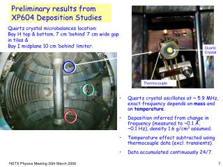
1.35 s Proton Beamline Extinction Cleanup • To eliminate prompt backgrounds, we need <10-9 proton beam extinction • Radio Frequency Modulated Magnet (RFMM) + Lambertson Magnets • Filled buckets • Arrival at RF dipole coincides with maximum field in the dipole • Beam is deflected into shielded channels in Lambertsons • Beam arriving out-of-time (empty buckets) • Receives less than maximal deflection in dipole, but opposite in sign • Enters diversion channels in Lambertsons • This RFMM is designed to divert an 8 GeV beam by 2 mrad, and to separate well the protons in filled and unfilled RF buckets. • Counter placed in the deflected beam after sufficient drift space downstream of the Lambertsons serves as a monitor of AGS internal extinction The field in the RFMM, showing phase of filled and unfilled buckets with respect to phase of the field. Chuan Chen, UC, Irvine
Concept Design of RF Modulator • The magnetization is phased to the proton beam using a signal from the AGS. A control system will allow the phase of the magnetization to be adjusted. • The power supplier will provide RF power. Commercially available power supplies typically have 50 out put impedance. A transformer will couple the PS to the magnet circuit and match impedance. • The magnet will be run as part of an LRC resonant network with a Q of ~100. A schematic drawing of the stripline magnet, which consists of current sheets with the current flowing in the directions indicated by the arrows. Chuan Chen, UC, Irvine
Parameters without and with a return yoke Two configurations studied: • Without flux return and a shaped current sheet to get good field uniformity. 2. With a flux return to reduce fringe fields and eddy current losses on vacuum enclosure, beam pipe, etc. Reduced power Higher inductance Chuan Chen, UC, Irvine
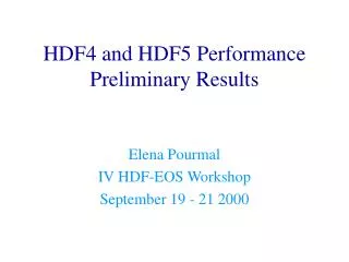
Properties of Ferrite Material • Ceramic Magnetics Inc. produces MN8CX material, a Mn-Zn ferrite developed for power converters operating in the range of 0.5 to 2 MHz at power level up to 500 gauss-MHz with extremely low loss and high stability. • The budgetary quote for the material is $0.50 per cm3, $0.75 if extensive machining of holes is required. The total volume of material is of order 140,000 cm3, so the total cost of material is rather modest. 75 G Power loss density vs. frequency Relative permeability vs. frequency Chuan Chen, UC, Irvine
Simulation in Elektra • Elektra is one of the analysis programs of the OPERA-3d Vector Fields Electromagnetic Analysis Environment. It can be used to compute electromagnetic fields including the effects of eddy currents. • Below is the cross section of the RF Modulated Magnet • The model used a single, 5 m long magnet. The conductor sheets are 10 cm wide, 2 mm thick and 5 m long. • Current frequency = 731 kHz • Model was run with peak current of 1200 A • Permeability of the return yoke was set to 1000o (MN8CX has value of ~3000 at 731 kHz) • Conductivity of the return yoke set to 0.001/(ohm-cm) (typical for MN8CX) Y X Z Chuan Chen, UC, Irvine
Results Chuan Chen, UC, Irvine
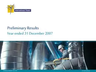
Results (continue) The left figure show the cumulative B field (B x Length / 100, Gauss•M) inside the module. The standard deviation in the two circles are 0.7 and 0.3. The width of the conductors is 8 cm instead of 10 cm since this can give more uniform B field. The distance between the conductors is 10 cm. Chuan Chen, UC, Irvine
Cooling System • Cooling, allowable operating temperature, allowed thermal gradients, etc. • We can put water pipes on the striplines and on the outer surface of the return yoke. Chuan Chen, UC, Irvine
Plans • Study the power loss in return yoke • Heating, thermal gradients, thermal stresses • Now the average power loss in return yoke 5.9 kW (about 1.2 kW for each module) • Method to decrease power loss (laminations) • Circuit design • We can use a 1m long coaxial cable to connect transformer and the striplines. Simple calculation tells us the capacitance, inductance, and resistance are at the same order that we want. • Impedance matching • The output impedance of the power supplier is 50 . Transformer will be designed to match impedance • Losses in all elements • The power losses are 400 w in transformer, 400 w in striplines, 200 w in coaxial cable and 1200 w in ferrite return yoke. This responds the quality factor to be 50 and it’s acceptable. We will work on optimizing this. • Model of electronic circuit (transformer, capacitor, magnet, leads) • Make electrical measurements to study impedance matching, correct resonant behavior • Two possible ways to let the LRC circuit to match the frequency changing • Put a small ferrite piece in the transformer and adjust its position to adjust total inductance. • Put two dielectric layers in the coaxial cable. One is fixed and the other is not. We can change the relative position of the two layer dielectrics to adjust the capacitance and the resonant frequency. • Structural and assembly design by mechanical engineer • Scale prototype of a module Chuan Chen, UC, Irvine