Download

1 / 37
370 likes | 544 Vues
Preliminary Conceptual Design Study of K-DEMO. June 26, 2013 Advanced Project Division National Fusion Research Institute kkeeman@nfri.re.kr. K-DEMO Tokamak Design. General Requirement (Two Phase Operation).

E N D
Preliminary Conceptual Design Study of K-DEMO June 26, 2013 Advanced Project Division National Fusion Research Institute kkeeman@nfri.re.kr
General Requirement (Two Phase Operation) • K-DEMO has two operation phases, Phase I and Phase II. Though the operation phase I K-DEMO does not need to demonstrate the competitiveness in COE(Cost of Electricity), the operation phase II K-DEMO need to demonstrate the competitiveness in COE. • All power core and plant subsystems in K-DEMO plant must be representative of those in the commercial plant. Extrapolation of technologies from K-DEMO to a commercial reactor should be straight forward. Practically all technologies to be used in commercial reactors should be demonstrated in the K-DEMO. Also, extrapolation of performance parameters between K-DEMO and commercial reactors should be minimized. • K-DEMO shall be operated and maintained with remote handling equipment. This is an absolute prerequisite as the neutron level during operation and radioactive activation during maintenance periods will be excessive for human intervention inside the power core building and hot cell bio-shields at all times • The operation phase II K-DEMO plant need to achieve an overall all plant availability larger than 70%. • The operation phase I K-DEMO is not considered as the final DEMO. It is a kind of test facility for a commercial reactor. But the operation phase II K-DEMO will require a major up-grade by replacing the blanket & divertorsystem and others if required. • Construction cost for K-DEMO should be minimized and the size of the K-DEMO Tokamak is expected to be smaller or similar size of ITER Tokamak. • The operation phase I K-DEMO • At initial stage, many of ports will be used for diagnostics for the operation and burning plasma physics study, but many of them will be transformed to the CTF (Component Test Facility). • At least more than one port will be designated for the CTF including blanket test facility. • It should demonstrate the net electricity generation (Qeng > 1) and the self-sufficient Tritium cycle (TBR > 1.05). • The operation phase II K-DEMO • Though there will be a major upgrade of In-Vessel-Components, at least one port will be designated for CTF for future studies. • It is expected to demonstrate the net electricity generation larger than 450 MWeand the self-sufficient Tritium cycle .
Optimization Concept of K-DEMO • Demonstrate a reasonable net-electricity (> 300 MW) generation with a minimum cost • Provide a maximum flexibility ARIES-AT CREST ARIES-RS K-DEMO (Stage II) PPCS-D SSTR ITER K-DEMO (Stage I)
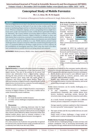
DEMO Small TF CICC Parameter • Cable Pattern: • (((2SC+2Cu)x5+2Cu)x6x6+Central Spiral) [360SC strand+432 Cu Strand] • Void Fraction : 27.1% • Strand : • High Jc (> 2600A/mm2) Nb3Sn Strand • Cu/Non-Cu = 1.0 • CentralSpiral : ID = 7mm OD = 9 mm • Insulation : 1.6 mm (with Voltage Tap) • 0.1 mm Kapton 400% • 0.3 mm S-glass 400% • Jacket Thickness : 5.0 mm • Twist Pitch • 1st Stage 80± 5 mm • 2nd Stage 140± 10 mm • 3rd Stage 190 ± 10 mm • 4th Stage 300 ± 15 mm • Wrapping Tape Thickness • Sub-cable : 0.08 m 40% • Sub-cablewrap width : 15 mm • Cable : 0.08 mm 200% • Final wrap width : 40 mm 1.6 5.0 R 3 Insulation 26.8 36.8 40.0 Jacket 26.8 36.8 40.0 DEMO TF Small CICC Cross-section
DEMO TF CICC Parameter(Option II) • Cable Pattern: • ((3SC)x4x5x6x5 + Helical Spiral) [1800 SC strand] • Void Fraction : 28.1% • Strand : • High Jc (> 2600A/mm2) Nb3Sn Strand • Cu/Non-Cu = 1.0 • HelicalSpiral : ID = 7 mm OD = 12 mm • Insulation : 1.6 mm (including Voltage Tap) • 0.1 mm Kapton 400% • 0.3 mm S-glass 400% • Jacket Thickness : 5.0 mm • Twist Pitch • 1st Stage 80± 5 mm • 2nd Stage 140± 10 mm • 3rd Stage 190 ± 10 mm • 4th Stage 245± 15 mm • 5th Stage 385± 20 mm • Wrapping Tape Thickness • Sub-cable : 0.08 m 40% • Sub-cable wrap width : 15 mm • Cable : 0.08 mm 140% • Final wrap width : 40 mm R 3 1.6 5.0 Insulation 58.8 68.8 72.0 Jacket 26.8 36.8 40.0 DEMO TF CICC Cross-section
Inboard Cross-Section of TF Coil (Option II) • Selected for Detailed Study (Maintenance Space = 2.5 m) • Considering Vertical and Horizontal Maintenance Scheme • R = 6.8 m, a = 2.1 m • Small CICC Coil : 20 x 9 turns Large CICC Coil : 12 x 5 turns (Total : 240 turns) • Magnetic Field at Plasma Center : ~7.4 Tesla (Bpeak ~ 16 Tesla, T-margin > 1 K) • Nominal Current : 65.52 kA • Conductor Length : • LQP = ~1020 m (Quadruple Pancake) (Total : ~495 ton) • SDP = ~930 m (Double Pancake) (Total : ~230 ton) Clearance Filled with Glass Fiber (5 mm) Ground Wrap (5 mm) 2150 mm 2565 mm 2925 mm 3135 mm 3220 mm
Outboard Cross-Section of TF Coil (Option II) 1018 mm Clearance Filled with Glass Fiber (5 mm) Space (Filled with 316) for Turn Transition and Feed Through (143 mm) 118 mm 150 mm Ground Wrap (5 mm) 550mm 13510 mm 220 mm 13595 mm 13795 mm 13948 mm 14308 mm 14528 mm
Inboard Cross-Section of TF Coil (Option II-alt) • Selected for Detailed Study (Maintenance Space = 2.5 m) • Considering Vertical and Horizontal Maintenance Scheme • R = 6.8 m, a = 2.1 m • Small CICC Coil : 18 x 10 turns Large CICC Coil : 12 x 5 turns (Total : 240 turns) • Magnetic Field at Plasma Center : ~7.4 Tesla (Bpeak ~ 16 Tesla, T-margin > 1 K) • Nominal Current : 65.52 kA • Conductor Length : • LQP = ~1020 m (Quadruple Pancake) (Total : ~495 ton) • SDP = ~1035 m (Double Pancake) (Total : ~230 ton) Clearance Filled with Glass Fiber (5 mm) Ground Wrap (5 mm) 2150 mm 2525 mm 2925 mm 3135 mm 3220 mm
Outboard Cross-Section of TF Coil (Option II-alt) 1018 mm Clearance Filled with Glass Fiber (5 mm) Space (Filled with 316) for Turn Transition and Feed Through (143 mm) 118 mm 190 mm Ground Wrap (5 mm) 550mm 13510 mm 180 mm 13595 mm 13795 mm 13948 mm 14348 mm 14528 mm
Joint Scheme of Inner Magnet From PS (or Inner Magnet Lead) To Neighboring Inner Magnet Lead Helium Feed Through Layer Transition Intercoil Joint Layer Transition Intercoil Joint Layer Transition
Joint Scheme of Outer Magnet From Outer (or Last Inner) Magnet Lead To Neighboring Outer Magnet Lead (orTo Power Supply)
In-Vessel Components Inboard blanket Semi-permanent inner shell Divertor module outboard blanket – port sector outboard blanket – TF sector Plasma components Plasma component segmentation
DEMO CS CICC Parameter (Corner Channel) • Cable Pattern: (2SC+1Cu)x3x4x4x6 [576 SC Strand + 288 Cu Strand] • Void Fraction : 35.85% • Strand : • ITER Type (Jc ~ 1000A/mm2) Nb3Sn Strand • Cu/Non-Cu = 1.0 • NO COOLING SPIRAL Corner Channel • Jacket Thickness : 5 mm • Insulation : 2.0 mm (with Voltage Tap) • 0.1 mm Kapton 400% • 0.4 mm S-glass 400% • Twist Pitch • 1st Stage 20 ± 5 mm • 2ndStage 45 ± 10 mm • 3rdStage 85 ± 10 mm • 4thStage 150 ± 15 mm • 5thStage 355± 20 mm • Wrapping Tape Thickness • Sub-cable : 0.08 mm 40% • Sub-cable wrap width : 15 mm • Cable : 0.5 mm 60% • Final wrap width : 7 mm R 3 2 5 Insulation 54 50 40 Jacket 34 30 20 DEMO CS CICC Cross-section
Cross-Section of CS Coils (Option II-CK) • Number of Turns : 14 (Total SC strand weight : ~102 tons) • Number of Layers : CS1, CS2, CS3 & CS4 : 24 layers • Magnetic Field at Center : ~11.8 Tesla (Bpeak < 12.194 Tesla) • Conductor Unit Length : 950 m (CS1, CS2, CS3 & CS4 : UL x 4) • Gap Between Coils : 104 mm • MagnetCenter Position : (1738, 700), (1738, 2100), (1738, 3500), (1738, 4900) 1296 mm 1500 mm 1976 mm CS3 Coils CS1 & CS2 & CS3 Coil
Magnetic Field of CS Coils (Option II) • Magnetic Field • Field at Center : ~11.8 Tesla • Peak Field : ~ 12.194 Tesla • Flux Swing (HalfSwing) : ~83 V·sec • Nominal Current : 42 kA (Current can be increased) • Temperature Margin ~ 1.3 K
Test Samples of Conductors DEMO CS CICC(corner channel) Small & LargeTF CICC
Concept of Vertical Maintenance (Pilot Plant) • Vertical maintenance of all in-vessel components for Pilot Plant (PPPL) Case Internal VV maintenance space expanded Enlarged TF Horizontal assisted maintenance VV (~150° C) Semi-permanent Inboard Shield structure (~350° C) Horizontal assisted maintenance DCLL PbLi/He Base Blanket (350/450° C) Gravity support / coolant supply plenum Coolant supply from below
Assumption for the Thickness of Blanket Inboard-Side Blanket [Thickness = 1050 mm] FW Blanket 28 200 150 50 59 302 75 31 155 Manifold& Structures Be Be Shield Li4SiO4 Structural Material Cooling channel W Be B4C Outboard-Side Blanket [Thickness = 1200 mm] FW Blanket 452 28 200 150 50 59 75 31 155 Manifold& Structures Be Be Shield
Inboard/Outboard-Side Blanket 54.8 100 100
Heating & Neutron/Photon Flux Be Be Be
Radial Build of K-DEMO [unit : mm] (Option II) Plasma CS TF VV Blan- ket Blanket VV TF 1500 TS SOL SOL TS 1976 Space for Vertical Maintenance 2150 3220 3420 3550 4600 4700 6800 8900 9000 10200 12700 13080 13510 14528
K-DEMO Conceptual Study & CDA Schedule Pre-study Memo for Pre-study Design Parameter Circulation & Modification Physics & Backup Study – Phase I Physics & Backup Study – Phase II Parameter Study & Conceptual Study Report Improvement of Report CDA & R&D Phase I CDA & R&D Phase II + CDR Target Date for K-DEMO Construction : End of 2037