Download
1 / 68
730 likes | 1.14k Vues
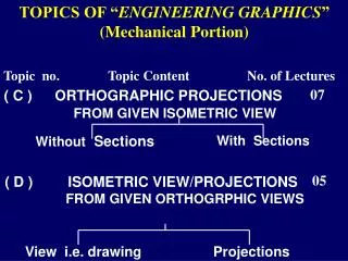
TOPICS OF “ ENGINEERING GRAPHICS ” (Mechanical Portion). Without Sections. With Sections. View i.e. drawing. Projections. Topic no. Topic Content No. of Lectures. 07. ( C ) ORTHOGRAPHIC PROJECTIONS FROM GIVEN ISOMETRIC VIEW. 05. ( D ) ISOMETRIC VIEW/PROJECTIONS

E N D
TOPICS OF “ENGINEERING GRAPHICS” (Mechanical Portion) Without Sections With Sections View i.e. drawing Projections Topic no. Topic Content No. of Lectures 07 ( C ) ORTHOGRAPHIC PROJECTIONS FROM GIVEN ISOMETRIC VIEW 05 ( D ) ISOMETRIC VIEW/PROJECTIONS FROM GIVEN ORTHOGRPHIC VIEWS
CONTINUOUS THICK A CONTINUOUS THIN (WAVY) B SHORT ZIGZAG THIN C CONTINUOUS THIN D D 40 D 30 SHORT DASH MEDIUM (DOTED LINE ) E F 25 LONG CHAIN THIN (CENTER LINE) D F A B E CUTTING PLANE LINE (IN F.V) 150 G1 G1 CUTTING PLANE LINE (IN T.V) G2 C 60 TYPES OF LINES USED IN ENGINEERING DRAWING APPLICATIONS OF LINES ON DRAWING
Dimensioning Techniques • Trimmed and untrimmed drawing sheet sizes are commercially designated as A0 (Maximum size), A1, A2, A3, A4 & A5 (Least size). • In Engineering Graphics’ term work, all the 4 sheets will be of A2 (approximately ½ Imperial) size • The following two systems are adopted for dimensioning purposes on orthographic views as well as on pictorial view.
20 35 20 H 3H 35 ALIGNED SYSTEM (FOR A2 TO A5 SHEET SIZE) UNIDIRECTIONAL SYSTEM (FOR LARGE SIZED SHEETS) ARROW HEADS (H x 3H)
ORTHOGRAPHIC PREOJECTIONS (MULTI VIEW REPRESENTATIONS i.e. F.V., T.V. & S.V. – L.H.S.V OR R.H.S.V) FROM ISOMETRIC VIEW • PLANES OF PROJECTIONS • QUADRANTS • VISION DIRECTIONS
VIEWES • METHODS OF PROJECTIONS WITH THEIR SYMBOLS • SCALING OF A DRAWING (Full Size 1:1, Reduced 1:2 or Enlarged 5:1 )
SCALING OF A DRAWING (AS PER BUREAU OF INDIAN STANDARDS FOR ENGINEERING DRAWING.) • RECOMMENDED SCALES • 1. FULL SCALEe.g. 1: 1 • In certain cases the engineering components may be very large or very small for drawing purposes, hence the corresponding scale may be preferred from the following
2. REDUCED SCALE e.g. 1:2, 1:2.5, 1:5, 1:10, 1:20, 1:15, 1:100, 1:200, 1:500, 1:1000, 1:2000, 1:5000, 1:10000 • 3. ENLARGED SCALE e.g. 50:1, 20:1, 10:1, 5:1, 2:1
SYMBOLS USED ON ENGINEERING DRAWING SHEET THIRD ANGLE METHOD OF ORTHOGRAPHIC PROJECTIONS FIRST ANGLE METHOD OF ORTHOGRAPHIC PROJECTIONS M/c. PARTS ARE NEVER ASSUMED IN SECOND OR IN FOURTH QUADRANT, AS THE VIEWS MAY OVERLAP ON ONE ANOTHER ABOVE XY OR BELOW XY RESPECTIVELY.
Y VP Y HP X X Z1 ISOMETRIC VIEW OF F.V. Plane L.H.S.V. Plane OBJECT IN FIRST QUADRANT (FOR L.H.S.V.) H F.V. L.H.S.V. H PP L D D L T.V. T.V. Plane FIRST ANGLE METHOD OF PROJECTIONS (FOR L.H.S.V.)
Fig. 2(c) shows turning of the planes H.P & P.P with their respective hinges, considering V.P as fixed plane. It may be noted that :- (a) F.V. (X directional view) is on V.P, T.V. (Y directional view) is on H.P, while L.H.S.V (Z1 directional view) is on P.P • F.V is within L & H, T.V is within L & D, While L.H.S.V is within H & D. • c) The symbol for Istangle method of projections is placed as shown on fig. 2(c)
V.P P.P F.V. Y X H.P H D L.H.S.V. L T.V. Fig. 2(c)
AIM: Fig. 2(a) shows the Pictorial (ISOMETRIC) view of a cut block. Draw its following orthographic views using Ist angle method of projections. • Front View • Top View • R. H. S.View
Y Y V.P P.P H X L D Fig 2(a) Y F.V. R.H.S.V. Y H.P T.V. H Z2 X L D Z2 X Fig 2(b)
Note : Ist angle means, the block is assumed in front of V.P, above H.P and inside P.P, as in fig. 2(b) where the F.V. is projected on V.P, seen in X direction, T.V. is projected on H.P, seen in Y direction & R.H.S.V. is projected on P.P, seen in Z2 direction
Fig. 2(c) shows turning of the planes H.P & P.P with their respective hinges, considering plane V.P as fixed plane. • It may be noted that :- • F.V. (X directional view) is on V.P, T.V. (Y directional view) is on H.P, while R.H.S.V (Z2 directional view) is on P.P • b) F.V is within L & H, T.V is within L & D, While R.H.S.V is within H & D. • c) The symbol for Istangle method of projections is placed as shown on fig. 2(c)
P.P V.P H D R.H.S.V. F.V. H.P L Y X T.V. Fig. 2(c)
AIM: Fig. 3(a) shows the Pictorial (ISOMETRIC) view of a cut block. Draw its following orthographic views using IIIrd angle method of projections. • Front View • Top View • Left Hand Side View
Y Y Y H H.P X L D X Z1 P.P Fig 3(a) T.V. D L H L.H.S.V. F.V. V.P Z1 X Plane H.P turned up(above V.P) Plane P.P turned side way(towards left side of plane V.P) Fig 3(b)
Note : IIIrd angle means, the block is assumed behind V.P, below H.P and inside P.P, as in fig. 3(b) where the F.V. is projected on V.P, seen in X direction, T.V. is projected on H.P, seen in Y direction & L.H.S.V. is projected on P.P, seen in Z1 direction
Fig. 3(c) shows turning of the planes H.P & P.P with their respective hinges, considering plane V.P as fixed plane. • It may be noted that :- • F.V. (X directional view) is on V.P, T.V. (Y directional view) is on H.P, while L.H.S.V (Z1 directional view) is on P.P • b) F.V is within L & H, T.V is within L & D, While L.H.S.V is within H & D. • c) The symbol for IIIrd angle method of projections is placed as shown on fig. 3(c)
4 T.V. Y X 6 2 L D H F.V. L.H.S.V Fig. 3(c)
AIM: Fig. 4(a) shows the Pictorial (ISOMETRIC) view of a cut block. Draw its following orthographic views using IIIrd angle method of projections. • Front View • Top View • Right Hand Side View
Y Y H.P X Y X Z2 D L T.V. Fig. 4(a) D L H H F.V. V.P R.H.S.V. P.P X Z2 Fig. 4(b) Planes H.P, V.P & P.P are assumed as transparent
Note : IIIrd angle means, the block is assumed behind V.P, below H.P and inside P.P, as in fig. 4(b) where the F.V. is projected on V.P, seen in X direction, T.V. is projected on H.P, seen in Y direction & R.H.S.V. is projected on P.P, seen in Z2 direction.
Fig. 4(c) shows turning of the planes H.P &P.P with their respective hinges, considering plane V.P as fixed plane. • It may be noted that :- • F.V. (X directional view) is on V.P, T.V. (Y directional view) is on H.P, while R.H.S.V (Z2 directional view) is on P.P • b) F.V is within L & H, T.V is within L & D, While R.H.S.V is within H & D. • c) The symbol for IIIrd angle method of projections is placed as shown on fig. 4(c)
H.P D T.V. P.P Y X L H R.H.S.V. F.V. V.P Fig. 4(c)
Step by step procedure Suggested to prepare Orthographic views (First angle method) for The simple component Shown pictorially in figure
20 20 40 20 60 80 Ø40 R40 100 20 ISOMETRIC VIEW X
20 20 R20 80 20 20 ø40 80 R40 100 R.H.S.V FRONT VIEW SYMBOLIS NOT MARKED SCALE: 1:1 TOP VIEW
FIGURE SHOWS ISOMETRIC VIEW OF A SIMPLE OBJECT(WITHOUT DIMENSIONS) SHOW ITS THREE ORTHOGRAPHIC VIEWS a • Front View • Top View • L.H.S.View b B 2 3 A Use First Angle Method c 1
b B 2 3 A 1 F.V L.H.S.V. a b c 3 T.V
FIGURE SHOWS ISOMETRIC VIEW OF AN OBJECT(WITHOUT DIMENSIONS) SHOW ITS THREE ORTHO GRAPHIC VIEWS a • Front View • Top View • L.H.S.View • Front View • Top View • L.H.S.View c 3 b A Use Third Angle Method 2 1
c a b TOP VIEW 3 A 2 1 FRONT VIEW L.H.S VIEW
Aim : Figure shows isometric view, of a simple machine component. Draw its following Orthographic views, & dimension them. • Front View • Top View • R.H.S. View Use First Angle Method of projection
L = 75+25=100 X H = 10+30=40 R25 D=50 20 30 10 10 40 10 75 Figure 50 Figure, is the isometric view
L=100 F.V H=40 L=100 T.V D=50 D=50 S.V H=40 10 40 10 R.H.S.V. F.V. 20 50 R25 10 40 25 75 ORTHOGRAPHIC VIEWS T.V.
40 SQ Ø30,Depth 10 25 SQ 10 30 15 SQ 35 5 10 35 5 40 ISOMETRIC ORTHO. VIEWS 45 15
10 30 5 10 35 45 35 15 40 Sq 25 Sq 40 10 5 15 Sq Ø30 F.V. R.H.S.V. T.V.
Exercise :- • Figure shows the isometric view of a vertical shaft support. • Draw its all the three views, using first angle method of projections. • Give the necessary dimensions as per aligned system.
Ø64 Ø40 24 50 25 10 140 20 48 ISOMETRIC VIEW
Ø40 Ø64 24 50 30 10 140 14 48 14 70 L.H.S.V FRONT VIEW TOP VIEW
Exercise :- Isometric view of a rod support is given. Draw its all the three orthographic views, using first angle method of projections. Give all the dimensions.
R22 40 Ø24 20 80 60 20 30 16 20 140 20 X 40 ISOMETRIC VIEW
R22 30 30 30 66 26 10 20 40 20 80 140 FRONT VIEW RIGHT SIDE VIEW SCALE: 1:1 TOP VIEW
20 R20 30 16 30 8 10 20 10 25 100 R8 45 ISOMETRIC ORTHO. VIEWS
R20 20 30 10 100 16 8 30 25 20 45 R8
SECTIONING OF A MACHINE COMPONENT BY ANY ONE SECTION PLA NE ,OUT OF THREE FOLLOWING MENTIONED SECTION PLANES
BY A VERTICAL SECTION PLANE • (PARALLEL TO PRINCIPLE V.P.) • Hence , • The real or true shape of the section is observed in its F.V. • Section plane will be seen as a cutting plane line (similar to center line ,thick at ends) with corresponding horizontal vision direction arrows at the center of thick ends in its T.V. & S.V.
(2)BY A HORIZONTAL SECTION PLANE • Hence, • The real or true shape of the section is observed in • its T.V. • (b) The cutting or section plane will be observed as a • cutting plane line (similar to center line ,thick at • ends) with the corresponding vertically downward • vision direction arrows at the center of the thick • ends in its F.V. and in S.V.