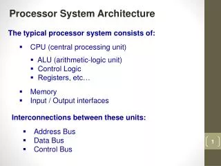
Processor Architecture
Processor Architecture. Topics. Sequential logic Suggested Reading: 4.2. Review. Computation Performed by combinational logic Computes “Boolean” functions Continuously reacts to input changes. I. O. Clock. Storage. Clocked Registers e.g. Program Counter(PC), Condition Codes(CC)


Processor Architecture
E N D
Presentation Transcript
Topics • Sequential logic • Suggested Reading: 4.2
Review • Computation • Performed by combinational logic • Computes “Boolean” functions • Continuously reacts to input changes
I O Clock Storage • Clocked Registers • e.g. Program Counter(PC), Condition Codes(CC) • Hold single words or bits • Loaded as clock rises • Not “program registers” • Clock • A periodic signal that determines when new values are to be loaded into the devices Clock Rising edge falling edge
Rising clock State = y y Output = y Register Operation State = x • Stores data bits • For most of time acts as barrier between input and output • As clock rises, loads input x Input = y Output = x
0 Comb. Logic 0 MUX 0 Out In 1 Load Clock A L U State Machine Example
0 Comb. Logic 0 MUX 0 Out In 1 Load Clock Clock Load A L U In Out State Machine Example ? X0 ? X0 • 1 X0
0 Comb. Logic 0 0 MUX Out In 1 Load Clock Clock Load A L U In Out State Machine Example X0 X0+X0 X0 X0 • 0 X0 X0
0 Comb. Logic 0 0 MUX Out In 1 Load Clock Clock Load A L U In Out State Machine Example X0 X0+X1 X0 X1 • 0 X1 X0 X0
0 Comb. Logic 0 MUX 0 Out In 1 Load Clock Clock Load A L U In Out State Machine Example X0+X1 X0+X1+X1 X0+X1 X1 • 0 X1 X0 X0 X0+X1
0 Comb. Logic 0 MUX 0 Out In 1 Load Clock Clock Load A L U In Out State Machine Example X0+X1 X0+X1+X2 X0+X1 X2 • 0 X1 X2 X0 X0 X0+X1
0 Comb. Logic 0 MUX 0 Out In 1 Load Clock Clock Load A L U In Out State Machine Example X0…X2 X0…X2+X2 X0…X2 X2 • 0 X1 X2 X0 X0 X0+X1 X0…X2
0 Comb. Logic 0 MUX 0 Out In 1 Load Clock Clock Load A L U In Out State Machine Example X0…X2 X3 X0…X2 X3 • 1 X1 X2 X3 X0 X0 X0+X1 X0…X2
0 Comb. Logic 0 MUX 0 Out In 1 Load Clock Clock Load A L U In Out State Machine Example X3 X3 X3 X3 • 1 X1 X2 X3 X0 X0 X0+X1 X0…X2 X3
0 Comb. Logic 0 MUX 0 Out In 1 Load Clock Clock Load A L U In Out State Machine Example • Accumulator circuit • Load or accumulate on each cycle X1 X2 X3 X4 X5 X0 X0 X0+X1 X0…X2 X3 X3+X4 X3…X5
Storage • Random-access memories • e.g. Register File, Memory • Hold multiple words • Address input specifies which word to read or write • Possible multiple read or write ports • Read word when address input changes • Write word as clock rises
valA Register file A srcA valW Write port Read ports W dstW valB srcB B Clock Register File • Register file • Holds values of program registers • %eax, %esp, etc. • Register identifier serves as address • ID “F” implies no read or write performed • Multiple Ports • Can read and/or write multiple words in one cycle • Each has separate address and data input/output
Register file Register file valW valW W W dstW dstW Clock Clock Register File Timing • Reading • Like combinational logic • Output data generated based on input address (After some delay) • Writing • Like register • Update only as clock rises valA 2 Register file x A srcA x valB srcB B 2 2 y 2 x Rising clock y 2
Memory • Memory • Holds program data and instructions • Ports • A single address input • A data input for writing, and a data output for reading • Error signal means invalid address data out error Data Memory read write Clock address data in
Summary • Storage • Clocked Registers • Hold single words (e.g., PC, CC) • Loaded as clock rises • Random-access memories • Hold multiple words (e.g., Register File, Memory) • Possible multiple read or write ports • Read word when address input changes • Write word as clock rises
Outline • SEQ timing • Organizing Processing into Stages • Suggested Reading 4.3.1 ~ 4.3.3
What is SEQ ? • SEQ: Sequential Processor • Y86 processor • Process a complete instruction in each cycle • What we have and we need? • Combinational logic and storage • ALU, Register File, Memory, PC, and CC
SEQ Components Combinational Logic Clocked Register Memory
SEQ Components Combinational Logic ALU Clocked Register Memory
SEQ Components Combinational Logic Combinational Logic Clocked Register Memory ALU
SEQ Components Combinational Logic Combinational Logic Clocked Register Memory Memory Register File ALU
SEQ Components Combinational Logic Combinational Logic Clocked Register Memory Memory Register File ALU
SEQ Components Combinational Logic Combinational Logic Clocked Register Memory CC Memory Register File ALU PC
SEQ Components Combinational Logic Combinational Logic Clocked Register Memory CC Memory Register File ALU PC
SEQ Components Combinational Logic Combinational Logic read write Clocked Register Memory CC write read Memory Register File ALU PC
SEQ Components • Combinational Logic • ALU • Control logic • Memory reads • Inst. memory • Data memory • Register file Combinational Logic read write Memory CC write read Register File ALU PC
SEQ Components • Sequential Logic • Program counter (PC) • Condition code (CC) • Register File • Memories • a single clock signal (All updated as clock rises) Combinational Logic read write Memory CC write read Register File ALU PC
Process Instruction on SEQ • SEQ • Process a complete instruction in each cycle • A single clock controls all states • Load CC and new PC • Write register file and memory The processor never needs to read back the state updated by an instruction in order to complete the processing of this instruction.
Beginning of Cycle 3 Cycle 1 Cycle 2 Cycle 3 Cycle 4 Clock 0x000: irmovl $0x100,%ebx # %ebx0x100 Cycle 1: 0x006: irmovl $0x200,%edx # %edx0x200 Cycle 2: addl %edx,%ebx # %ebx0x300 CC000 0x00c: Cycle 3: 0x00e: je dest # Not taken Cycle 4:
Beginning of Cycle 3 0x006: irmovl $0x200,%edx # %edx0x200 Cycle 2: Combinational Logic • state set according to 2nd instruction • PC: 0x00C • CC: 100 (assume) • %edx: 0x200 • %ebx: 0x100 • combinational logic starting to react to state changes read write Memory 100 write read ALU Register File %ebx=0x100 %edx=0x200 0x00C
End of Cycle 3 Cycle 1 Cycle 2 Cycle 3 Cycle 4 Clock 0x000: irmovl $0x100,%ebx # %ebx0x100 Cycle 1: 0x006: irmovl $0x200,%edx # %edx0x200 Cycle 2: addl %edx,%ebx # %ebx0x300 CC000 0x00c: Cycle 3: 0x00e: je dest # Not taken Cycle 4:
End of Cycle 3 addl %edx,%ebx # %ebx0x300 CC000 0x00c: Cycle 3: Combinational Logic • state set according to 2nd instruction • combinational logic generates results for 3rd instruction read write Memory 100 write read ALU 000 Register File %ebx=0x100 %edx=0x200 %ebx0x300 0x00C 0x00E 0x00C
Beginning of Cycle 4 Cycle 1 Cycle 2 Cycle 3 Cycle 4 Clock 0x000: irmovl $0x100,%ebx # %ebx0x100 Cycle 1: 0x006: irmovl $0x200,%edx # %edx0x200 Cycle 2: addl %edx,%ebx # %ebx0x300 CC000 0x00c: Cycle 3: 0x00e: je dest # Not taken Cycle 4:
Beginning of Cycle 4 0x00e: je dest # Not taken Cycle 4: Combinational Logic • state set according to 3rd instruction • PC: 0x00E • CC: 000 • %edx: 0x200 • %ebx: 0x300 • combinational logic starting to react to state changes read write Memory 000 write read ALU Register File %ebx=0x300 %edx=0x200 0x00E
End of Cycle 4 Cycle 1 Cycle 2 Cycle 3 Cycle 4 Clock 0x000: irmovl $0x100,%ebx # %ebx0x100 Cycle 1: 0x006: irmovl $0x200,%edx # %edx0x200 Cycle 2: addl %edx,%ebx # %ebx0x300 CC000 0x00c: Cycle 3: 0x00e: je dest # Not taken Cycle 4:
End of Cycle 4 0x00e: je dest # Not taken Cycle 4: Combinational Logic • state set according to 3rd instruction • combinational logic generates results for 4th instruction read write Memory 000 write read ALU Register File %ebx=0x300 0x00E 0x013 0x00E
How to design SEQ ? • Naïve Design: One-by-one • Straightforward, but waste • Advanced Design: Multi-stages • Formulate instruction execution as sequence of simple steps (stages) • Like: function for programming • Best use of hardware • Challenge: use same general form for all instructions
Optional Optional D icode 5 0 rA rB ifun rA rB valC Y86 Instruction Decoding • Instruction Format • Instruction byte icode:ifun • Optional register byte rA:rB • Optional constant word valC
0 1 2 3 4 5 0 0 6 0 1 0 6 1 2 2 fn 0 rA rA rB rB 6 2 3 0 F rB 6 3 4 0 rA rB 5 0 rA rB 2 1 6 fn rA rB 2 2 2 3 2 4 2 5 2 6 Y86 Instruction Set Byte cmovle nop cmovl halt cmove rrmovl rA,rB cmovne cmovl rA,rB cmovge irmovl V,rB V cmovg rmmovl rA,D(rB) D addl mrmovl D(rB),rA D subl OPl rA, rB andl xorl
0 1 2 3 4 5 jmp 7 0 jle 7 1 jl 7 2 7 fn je 7 3 8 0 jne 7 4 9 0 jge 7 5 A 0 rA F jg 7 6 B 0 rA F Y86 Instruction Set Byte jXX Dest Dest call Dest Dest ret pushl rA popl rA
int nexti(argc, argv) { /* get code and function */ /* get register and immediate */ /* execute */ swith(icode){ /* alu + r/w mem + w reg */ pc = next_pc; } } /* do alu */ long_t compute_alu(op, regA, regB) {} /*get memory */ Val = get_mem_val(m, addr) {} /*set memory */ set_mem_val(m, addr, val) {} /* set regs */ set_reg_val(rf, id, val) {} Lab5: Y86sim 1 2 example: pushl %edx 1: get icode: a get ifun: 0 2: get regA: reg[%edx] get regB: reg[F] 3: addr: reg[%esp]-4 4: set mem: reg[%edx] 5: set reg: reg[%esp] 6: pc: pc + 2 6 3 4 5
Instruction Execution Stages • Fetch • Read instruction from instruction memory • Decode • Read program registers • Execute • Compute value or address • Memory • Read or write data • Write Back • Write program registers • PC • Update program counter
Data memory ALU PC increment PC Write back Memory CC CC Execute Decode A B Register File M E M Register Instruction memory Instruction Fetch PC
SEQ Hardware Structure • Instruction Flow • Read instruction at address specified by PC: 1 • Process through stages: 25 • Update program counter: 6