Download
1 / 37
370 likes | 567 Vues
Mars Atmosphere and Volatile EvolutioN (MAVEN) Mission. Particles and Fields Package Peer Review May 8 -10, 2011 Christopher Smith, Thermal Engineer. Initial Work Flow. UCB builds individual instrument thermal models SWIA, STATIC, SEP, LPW, PFDPU, and SWEA

E N D
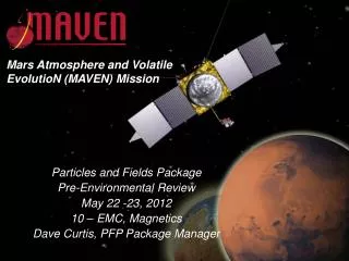
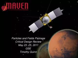
Mars Atmosphere and Volatile EvolutioN (MAVEN) Mission Particles and Fields Package Peer Review May 8 -10, 2011 Christopher Smith, Thermal Engineer
Initial Work Flow UCB builds individual instrument thermal models SWIA, STATIC, SEP, LPW, PFDPU, and SWEA UCB submits these models to spacecraft provider (LM) who incorporates them into the spacecraft thermal model. LM generates sink couplings for each instrument node for environments and delivers these to UCB UCB incorporates LM environments and goes through a design cycle to meet ERD requirements. UCB returns new generation of instrument models to LM. Cycle repeats as necessary LM responsible for producing official predicts for mission
Interface Issues LM unhappy with UCB thermal models LM required, and UCB agreed to, ~50 node instrument models UCB thermal engineer provided ~200 to 300 node instrument models LM chooses to reduce UCB thermal models in house due to limited thermal support by UCB at the time LM provides results and sinks back to UCB for the reduced instrument model UCB not happy because this requires a lot of monkeying around to get to work with full instrument models UCB not happy with only hot and cold case sinks provided LM reduced thermal models contain potential for error as they were not produced by UCB After much discussion LM releases full spacecraft model for use by the instrument teams Includes their full case set definitions
Current Work Flow UCB builds individual instrument thermal models (DONE) SWIA, STATIC, SEP, LPW, PFDPU, and SWEA LM provides sink temperatures for UCB boundary node spacecraft UCB modifies instruments to meet requirements in all provided environments (DONE) UCB submits these models to spacecraft provider (LM) who incorporates them into the spacecraft thermal model. (DONE) LM returns spacecraft thermal model with integrated instrument models (DONE) LM had some issues, so far it looks like they are all modeling problems with the reduced instrument models (IN PROGRESS) UCB uses spacecraft model to address any issues and returns updates to LM (IN PROGRESS) LM responsible for producing official predicts for mission
Current Status Not yet at CDR level with instrument predicts (Complete By CDR) Spacecraft model running at UCB with full instrument models integrated All the gross errors are worked out but needs more work to assure everything is running well Deep Dip and Thruster heating still in spreadsheet form (Complete By CDR) Spacecraft case sets include proper deep dip environments Need to add thruster heating LPW boom thermal treatment un-resolved Black Nickel originally specified but it alters the mechanical behavior of the boom DAG 213 a possibility but susceptible to AO degradation Without a high emissivity surface stacer over heats in deep dips PFDPU board analysis not complete (Complete By CDR?) RBSP LVPS board overheating No real board level thermal analysis done for RBSP Issues with RBSP need to be addressed on PFDPU boards
Environmental Loads Values above from LM Case Sets Thruster flux combination of ACS and TCM firings
Optical Properties All Materials approved by GSFC and JPL on previous missions Added testing for AO exposure Clear Alodine done by one plater with specified soak time. Extensive sampling with THEMIS. Occasional sampling with other missions. Wide BOL/EOL variance assumed in design
Thermophysical Properties Values above from LM Case Sets Thruster flux combination of ACS and TCM firings
SWIA Thermal Model Germanium Black Kapton Blanket Black Nickel + Grid (Not Shown) Blanket, 1.5 Sides Black Nickel Power Dissipation: 1.85 W +/- 15% Mass: 2.5 kg Conduction to SC Isolated 4 #8 Titanium with .25" G10 Isolator = .013 W/C each
STATIC Thermal Model Germanium Black Kapton Blanket Black Nickel + Grid (Not Shown) Blanket, 1 Side Black Nickel Power Dissipation: 3.96 W +/- 15% Mass: 2.9 kg Conduction to APPIsolated 4 #8 Titanium with .25" G10 Isolator = .013 W/C each
SWEA Thermal Model Blanket Black Nickel 50 % Blanket 50% Black Nickel Power Disipation: .89 W +/- 15% Mass: 1.8 kg SC Balance Mass: ~ 17 kg Conduction to SC Isolated 4 #8 Titanium with .25" G10 Isolator = .013 W/C each Blanketed Balance Mass
SEP Thermal Model Blanket White Paint, Z-93-C55 Power Disipation: .016 W +/- 15% Mass: .63 kg White Paint, Z-93-C55 Conduction to SC Isolated 4 #8 Titanium with .25" ULTEM 1000 Isolator = .011 W/C each
PFDPU Thermal Model Black Nickel? Boards to Frame Conduction: Epoxied to frame at lip = .386 W/C 8 #4 Screws (screw path only)=.1 W/C total Frame Conduction to Adapter Plate: 22 #6 screws 0.42 = 9.24 W/C Adapter Plate Conduction to SC: 6 #10 bolts 1.32 each = 7.92 W/C Simple Distributed Board Models Power Disipation: 12.1 W +/- 15% Mass: 5.9 kg
LPW Thermal Model Whip PreAmp Power: .015 W +/- 15% Stowed Stacer and DAD Mass: 2.6kg Base Mech to Bracket Conductance: 6 #8 Ti with .25" G10 Isolator = .013 W/C each
LPW Thermal Model Clear Alodine (Inside Spacecraft Body Blanket) DAG 213? Titanium Nitride
Spacecraft Thermal Model Full Spacecraft Model • Boundary Node Spacecraft • All Surface Temps from LM Output • MLI Unbound
Lockheed Thermal Memos #1 • STATIC Modeling problem fixed, now looks ok • SEP modeling issue found, LM Notified and producing new predicts
Lockheed Thermal Memos #2 • No Issues, but not yet correlated with UCB run
Lockheed Thermal Memos • No Issues, but not yet correlated with UCB run
RBSP LVPS Thermal Issue PWM chip on RBSP LVPS was running 60 C above the box temp and was running at 90 C before thermal vac test was aborted Investigation revealed several issues Board mounting standoffs were G10 instead of Aluminum EMI shield was Alodined Aluminum shutting off radiation More importantly ground / thermal planes did not connect to the mounting areas
RBSP Resolution RBSP issue solved Removed resistors dissapating1 watt from board, will mount to side of box Turned radiation back on with black paint Built a detailed thermal model of board and correlated its performance with testing 12 layer FR4 board 12 layers of FR4 in Model .093” / 12 = 0.00775” thick Conductors between FR4 layers Board contains 7, 3-oz Ground Planes All ground planes are partial though they cover most of the board 7 Separate ground planes in model 0.0042” thick Conductors from each ground layer to the FR4 layer above and the layer below Individual components dissipating more than .1 W modeled
PFDPU Way Forward Create detailed thermal model of high dissipation boards Current simple distributed property model is a good start Thermal / Ground planes need to grow as much as possible and overlap as much as possible. Thermal planes need to be brought to the edge of the board Maintain electrical isolation while improving thermal connections much as possible
LPW Stacer LPW Stacer needs to be black to help reject deep dip heat load Black Nickel was identified as a candidate and sent out for AO testing and it did well However when it was applied to a stacer it modified its mechanical behavior DAG 213 was identified as an alternative We have lots of experience with it and has been used on stacers before Unfortunately DAG 213 was completely eroded after AO testing
Backup Slides Back Up Slides
Requirements Documents Performance Requirements Document MAVEN-program-plan-appendix-v28_L1Req.doc (Level 1) MAVEN-PM-RQMT-0005, Mission Requirements (Level 2) MAVEN-PFIS-RQMT-0016, PFP Requirements (Level 3) MAVEN-PF-STATIC-001A-Requirements_&_Specifications.xls (Level 4) Mission Assurance Requirements MAVEN-PM-RQMT-0006, Mission Assurance Requirements MAVEN_PF_QA_002, PFP Mission Assurance Implementation Plan Mission Operations MAVEN-MOPS-RQMT-0027, Mission Operations Requirements Environmental Requirements Document MAVEN-SYS-RQMT-0010 Spacecraft to PFP ICD MAVEN-SC-ICD-0007
LM Science Case Definitions Science Cases Deep Dip Cases