Download
1 / 46
460 likes | 697 Vues
Mars Atmosphere and Volatile EvolutioN (MAVEN) Mission. Particles and Fields Package Pre-Environmental Review May 22 -23, 2012 Thermal Millan F. Diaz-Aguado. Thermal PER Outline. Thermal Design Update Thermal Analysis Status CDR RFA’s Changes since CDR

E N D
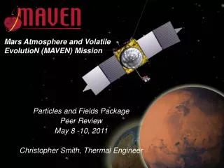
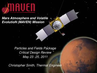
Mars Atmosphere and Volatile EvolutioN (MAVEN) Mission Particles and Fields Package Pre-Environmental Review May 22 -23, 2012 Thermal Millan F. Diaz-Aguado
Thermal PER Outline Thermal Design Update Thermal Analysis Status CDR RFA’s Changes since CDR Assumptions (Environmental Loads, Power Dissipation, Optical Properties) Goddard Thermal Golden Rules Test Temperatures Thermal Analysis Status and Results Thermal Status General Thermal Balance and Thermal Vacuum Test Plans Thermal Facilities Facilities Schedule Documentation Other Thermal Testing
Thermal Design Update • Changes since CDR • LPW • Reduced operational heater set-point to -15ºC (old set-point 0ºC) • PFDPU • Wet mount to S/C • No survival heater necessary • SEP • Reduced operational heater set-point to -45ºC (old set-point -35ºC) • STATIC • Thermally coupled to APP through eGRAF • Radiator is now white paint (Z93 C55), previously black nickel • SWEA • Reduced radiator size, increased MLI • Radiator is now white paint (Z93 C55), previously black nickel • SWIA • Increased radiator size and thermally coupled to S/C through eGRAF • Radiator is now white paint (Z93 C55), previously black nickel *Radiators Painted at NASA Goddard **eGRAF donated by NASA Goddard
CDR RFA’s • RFA001 – Thermal Optical Properties: Closed • RFA002 – Thermal Analysis Reports: Closed • RFA003 – Thermal cycling of LPW: Closed • RFA009 – Heater duty cycle may exceed GSFC Gold Rule of 70%: Closed
Thermal Analysis Status • Coordination with Lockheed Martin • Closely working with LM, Marc Church and Bret Sharp • Meetings led by Dan Powers • Delivered PF model to LM for incoporation into S/C • Received S/C model from LM for analysis use • Updated PF Instruments in model • Analysis Cases Run • Running all cases from S/C model (Acquisition, Cruise, MOI, Science, Deep Dips and Relay) • Not running launch cases
Power Dissipation Assumptions • Hot Case – Measured power dissipation • Cold Case- Measured power dissipation -10%
Values above from LM Case Sets Environmental Loads
All Materials approved by GSFC and JPL on previous missions Clear Alodine done by one plater with specified soak time. Extensive sampling with THEMIS. Occasional sampling with other missions. Wide BOL/EOL variance assumed in design Optical Properties
Thermal Golden Rules If Heater Controlled +15ºC +10ºC +5ºC PF Predicted Temperature PT FA AFT AFT PF FA -5ºC -10ºC -15ºC
Temperature Limits • PF Max/Min are +/-10ºC more than AFT • All instruments will be tested to PF * Heater Controlled
Operational Analysis Smallest Temperature Margins (ºC) Science Cruise Deep Dip Relay AFT Pending change of ERD Thermal
Survival Analysis Smallest Temperature Margins (ºC) - MOI, Cruise Safe Mode, Science Safe Mode and Acquisition Non Operational Temperatures 1.9 ºC above AFT AFT Thermal
LPW Temperatures • Before Deployment (non operational) • Deployment (operational) • After Deployment (non operational) Break Golden Rules Note: Heater non-operational Thermal
Thermal Analysis Status Heater Power Budget Need at least 30% Duty Cycle Margin on Individual Heaters LPW Deployment *Setpoint decreased to -15ºC (from 0ºC) Thermal
Thermal Status • LPW • Heaters installed and verified • PFDPU • Black Anodized • SEP • Painted, heaters in stock, Ultem in stock • STATIC • Radiator painted, heaters in stock, eGRAF in stock • SWEA • Radiator painted, heater in stock, G-10 in stock • SWIA • Radiator painted, heaters installed and verified, eGRAF in stock
Thermal Vacuum,Thermal Balance and Bakeout • Survival Cycle • Thermal Vacuum first cycle (SWIA, STATIC, SWEA have the same survival/operational temperatures) • Heater functional at first survival cold cycle • Thermal Balance* • Extended hot/cold soak on a Thermal Vacuum cycle at operational temperature • Break vacuum if necessary to uninstall thermal isolators (SEP, SWEA) after TB • Thermal Vacuum cycling • Eight Cycles • Ramp rates between 1ºC/min and 2ºC/min. • Soak times 4 hours within 3ºC from plateau (or less than 1ºC/hr. temperature change) • Heater functional at first operational cold cycle • Bakeout • Extend last cycle to obtain 48 hours of bakeout at high temperature • Flight MLI will be used during testing during thermal vacuum tests • STATIC, SEP, SWEA will have flight MLI blankets (*Thermal Balance) • LPW and SWIA will not have MLI blankets and will not be thermally balanced at instrument level • PFDPU does not have an MLI blanket and will not be thermally balanced at subsystem level
Thermal Vacuum/Balance/Bakeout Profile Bakeout Operational Cycle Survival/Balance* Cycle Turn on/off Turn on, TB Turn off Chamber Break Turn on, TB Operational Heater Functional Survival Heater Functional
Thermal Facilities • Bay Side • Pressure range: down to 1e-6 Torr • Temperature range: -60ºC to 90ºC • Transition rates 1 to 2ºC/min • Clean room access and ESD benches • Interlock, fail-safe valves • TC Channels – 16, silicon diode reference • Currently with 6 DB-25 ports (configurable) • Over-temperature alarms • Liquid nitrogen cooled • Used for THEMIS • TQCM available • Nitrogen gas backfill • Snout 1 and 2 • Pressure range: down to 1e-6 Torr • Transition rates 1 to 2ºC/min • Temperature range: -70ºC to 90ºC • Small cold finger down to -180ºC • TC Channels – 32, silicon diode reference • Currently with 5 DB-25 ports (configurable) • Clean tent access • Over-temperature alarms • Liquid nitrogen cooled • Used for THEMIS, RBSP • TQCM available on Snout 2 • Nitrogen gas backfill • Bertha • Backup, larger chamber
T-Vac Chamber Instrument Interface SWIA STATIC Thermal
Pass Criteria • Test will be considered successful if the following criteria are met: • Completion of the thermal balance testing and collection of all data • Thermal engineer approval of balance data vs. model predicts • Successful performance of each CPT and LPT • Proper functionality of all survival and operational heater circuits • Passing a post-test inspection • No loss of functionality observed such as changes in: • Instrument or component power draw • Detector signals or noise levels • Instrument thermal performance
Facilities Schedule Subsystem or Instrument Chamber Bay Side SWEA SEP STATIC Snout 1 SWIA PFDPU Snout 2 LPW Bertha Backup Chamber July August
Other Thermal Testing • Heater Installation Verification • IR image of functional heater post installation
June Work • Prepare chambers by July • Assemble clean tent for Snout 1-2 • Clean clean-room for Bayside chamber • Build GSE feed-throughs • Bakeouts of chambers • Thermal Balance Model • Finalize TC locations • Finish thermal vacuum documentation
Summary • Heater budget well understood • Temperatures understood, maybe some modifications needed to tests limits • Documents are in draft form, need to complete • Testing chambers scheduled and available • Preparations needed for testing
Thermal Design • STATIC MLI Black Nickel MLI MLI MLI MLI White Paint Heaters (under MLI) Cotherm (8W/C) Thermal
Thermal Design – STATIC Radiator • Area Painted White: 17.64 in² • Area Painted White in Model: 17.59 in² • Just changed the area painted (previously 20 in²) Thermal
Thermal Design • SWIA White Paint MLI MLI Black Nickel MLI MLI Heaters (under MLI) Cotherm (8W/C) Thermal
Thermal Design - SWIA Radiator • Area Painted White: 16.59 in² • Area Painted White in Model: 16.4 in² (previously 14.1 in²) Thermal
Thermal Design • SWEA MLI Black Nickel MLI MLI White Paint G10 – Standoffs (0.52 W/C) MLI Heaters Inside Thermal
Thermal Design - SWEA Radiator • Actual radiator is ½ of the cylindrical surface: 9.75 in² • Model radiator is 9.7 in² Thermal
Thermal Design • LPW LPW Black Nickel DAG213 Titanium Nitride Heater For Deployment Only 0.3 (W/C) Wet Contact (8W/C) Thermal
Thermal Design • SEP MLI White Paint White Paint Heater (inside cover) White Paint Ultem Standoffs (0.33W/C) Thermal
Thermal Design • PFDPU Black Anodize Wet Mount (NuSil?) (4.6W/C) Thermal
Cruise Temperatures Thermal
Science Temperatures *SEP is heater controlled Thermal
Deep Dip Temperatures Thermal
Relay Temperatures Thermal
Safe Modes and Instruments Powered Off Temperatures *SWIA 1.9ºC above AFT in 1002 Initial Acquisition Thermal
Cruise Heater Power Thermal
Science Heater Power Thermal
Deep Dips Heater Power Thermal
Relay Heater Power Thermal
Survival Heater Power Cases 1001 and 1002 do not need any heater power Thermal