Download
1 / 21
361 likes | 927 Vues
BUILDING CONSTRUCTION V ARCHITECTURAL FINISHING SYSTEMS. 5.0. 5.0 ARCHITECTURAL FINISHING SYSTEMS 5.1 SUSPENDED LIGHT GAUGE CEILING SYSTEM. 5.1. 5.0. 5.1. 5.0. 5.1. 5.0. 5.2 RAISED FLOOR SYSTEMS (ACCESS FLOORS). 5.2. 5.0. 5.2. 5.0. 5.2. Horizontal channel bracing

E N D
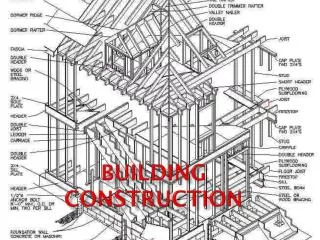
BUILDING CONSTRUCTION V ARCHITECTURAL FINISHING SYSTEMS
5.0 5.0 ARCHITECTURAL FINISHING SYSTEMS 5.1 SUSPENDED LIGHT GAUGE CEILING SYSTEM 5.1
5.0 5.1
5.0 5.1
5.0 5.2 RAISED FLOOR SYSTEMS (ACCESS FLOORS) 5.2
5.0 5.2
5.0 5.2
Horizontal channel bracing Walls less than 10’ (3050) high: Walls over 10’ (3050) high: • 2 rows @ 1/3 height for vertical loads • 1 row @ mid-height for wind loads • 3’-4” (1015) o.c. maximum for vertical loads • 5’-0” (1525) o.c. maximum for wind loads 5.0 5.3 LIGHT-GAUGE STEEL STUDS Light-gauge steel studs @ 12”, 16” or 24” (305, 405 or 610) o.c. 5.3 Continuous runner channel Diagonal steel strap bracing welded to studs and runners Light-gauge steel stud assembly @ corners Secure strap connection to stud and runner with a steel gusset plate or welds Angle clip welded to stud and bolted foundation Splice runner sections with a stud section
5.0 Light-gauge stud walls are framed, sheathed, insulated and finished as in wood light frame construction Channel studs Light-gauge steel studs are usually prepunched to allow piping, wiring and bracing to pass through Consult manufacturer for specific shapes and available sizes and gauges 5.3 Connections are made with self-drilling, self-tapping screws inserted with an electric or pneumatic tool or with pneumatically driven pins C-Studs 1”, 1-3/8” (25, 35) thick 2-1/2”, 3-1/4”, 3-5/8”, 4”, 6” (64, 85, 90, 100, 150) wide 1-1/4”, 1-3/8”, 1-1/2”, 1-5/8” (32, 35, 38, 41) thick 2-1/2”, 3”, 3-1/2”, 3-5/8”, 4”, 5-1/2”, 6”, 7-1/2”, 8” (64, 75, 90, 100, 140, 150, 190, 205) wide
Light-gauge steel studs 5.0 Continuous runner channel Light gauge steel joists Overhang possible Web stiffeners 5.3 Continuous runner Perimeter channel Light-gauge steel studs @ 12”, 16” or 24” (305, 405 or 610) o.c. Exterior wall sheathing and finish Horizontal channel bracing Continuous runner channel Light-gauge steel joists Perimeter channel fastened to web stiffeners and clip angles Web stiffener Clip angle anchor bolted to concrete foundation wall
5.0 Provide web stiffeners for steel joists that continue over support Light-gauge steel studs Continuous runner channel Light-gauge steel joists Reinforced concrete on metal decking 5.3 Double channel Continuous runner channel Open-web steel joists Light-gauge stud bearing wall Steel beam or light-gauge stud bearing wall EXTERIOR WALL INTERIOR WALL STUD ASSEMBLY AT PARTITION INTERSECTION STUD ASSEMBLY AT EXTERIOR CORNER
5.0 Steel gusset plate 5.3 Trussed header Structural steel channel Double C-joists Trussed bridging at corners next to openings Double or nested studs
5.0 5.3 • Nominal depths: 6”, 8”, 10”, 12”, 14” (150, 205, 255, 305, 355) • Flange widths: 1-1/2”, 1-3/4”, 2”, 2-1/2” (38, 45, 51, 64) • Gauges: 14 through 22 NESTABLE JOIST ‘C’ JOIST JOIST CLOSURE TYPES OF LIGHT-GAUGE STEEL JOISTS
5.0 Wood panel deck Steel joist continues or laps with adjoining joist over beam or wall support 3” (75) minimum bearing at interior supports 5.3 Web stiffener Double joists under partition loads INTERIOR BEARING Metal stud wall Continuous runner fastened through deck to closure channel Perimeter closure channel Web stiffener 1-1/2” (38) minimum bearing at joist ends Steel joists Metal stud bearing wall EXTERIOR BEARING
5.0 5.4 METAL CLADDING ALPOLIC & ALPOLIC®/fr Interior and Exterior Interior ALPOLIC® Features Lightweight and Rigid Interior ALPOLIC® is a light and strong sheet material. With the light specific gravity of 1.2 it can reduce weight by 40% compared with solid aluminum sheet and by 70% of stainless steel with the equivalent rigidity. Continuous laminating process to laminate aluminum skins and core material provides the excellent flatness of the panel free of distortion and deflection. Cutting, bending, curving and other procedures are easily accomplished with aluminum working or wood working machines. Compared with calcium silicate board and gypsum board, Interior ALPOLIC® cannot be cracked and broken because of lamination with aluminum skins and visco-elastic high molecular resin. Compared with other materials of the same weight (steel, aluminum, plywood, etc.) Interior ALPOLIC ® has a larger sound transmission loss. The coatings are applied with a continuous coil coating line, and consistent coating quality and hence, high performance can be expected in corrosion resistance and weather-ability in ALPOLIC ® PC Series and ALPOLIC ® PC Stone Series, which can be applied for moist rooms. Interior ALPOLIC ® has a good thermal insulation effect due to the core material of high molecular resin. 5.4 Flatness Workability Impact Resistance Sound Transmission Corrosion Resistance, Humidity Resistance and Weather-ability Thermal Insulation
5.0 ALPOLIC® 5.4
5.0 Exterior ALPOLIC®/fr Features Superior Flatness The continuous laminating process that combines 0.5 mm thick aluminum skins with the core material results in excellent flatness of the panel. The unique technology of the coil coating process provides the best quality of color uniformity, and no visible surface grain lines. A light and strong sheet material with an apparent specific gravity of 1.2 to 2.0, reducing weight by 40% (ALPOLIC®) to 15% (ALPOLIC®/fr) compared with solid aluminum sheet with equivalent rigidity. ALPOLIC®/fr and ALPOLIC® are resistant to reasonable impact loads due to the unique composite composite construction of strong aluminum skins bonded to a viscoelastic core. Cutting, bending, curving, routing, grooving and other procedures are easily accomplished with aluminum working or woodworking machines. ALPOLIC®/fr meets fire code requirements because of its non-combustible mineral filled core. 5.4 Excellent Color Uniformity Rigidity Impact Resistance Workability Fire Resistance
5.0 5.4 Damansara Mosque Kuala Lumpur, Malaysia Fluorocarbon Paint, Metallic PLDT Makati, Philippines Fluorocarbon Paint, Metallic Hewlett Packard Building Los Antos, CA, USA Fluorocarbon Paint, Solid 400 George Street Sydney, Australia Fluorocarbon Paint, Metallic
5.0 5.4 * Indicates that this method is not available with A-LOOK®
5.0 5.4