Interconnection Networks for Multiprocessors
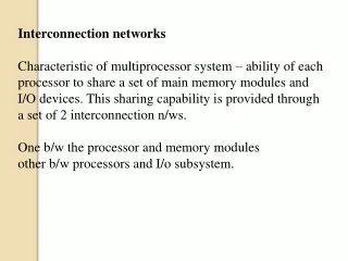
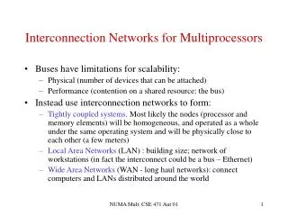
Interconnection Networks for Multiprocessors. Buses have limitations for scalability: Physical (number of devices that can be attached) Performance (contention on a shared resource: the bus) Instead use interconnection networks to form:

Interconnection Networks for Multiprocessors
E N D
Presentation Transcript
Interconnection Networks for Multiprocessors • Buses have limitations for scalability: • Physical (number of devices that can be attached) • Performance (contention on a shared resource: the bus) • Instead use interconnection networks to form: • Tightly coupled systems. Most likely the nodes (processor and memory elements) will be homogeneous, and operated as a whole under the same operating system and will be physically close to each other (a few meters) • Local Area Networks (LAN) : building size; network of workstations (in fact the interconnect could be a bus – Ethernet) • Wide Area Networks (WAN - long haul networks): connect computers and LANs distributed around the world NUMA Mult. CSE 471 Aut 01
Switches in the Interconnection Network • Centralized (multistage) switch • All nodes connected to the central switch • Or, all nodes share the same medium (bus) • There is a single path from one node to another (although some redundant paths could be added for fault-tolerance) • Distributed switch • One switch associated with each node • And of course, hierarchical combinations NUMA Mult. CSE 471 Aut 01
Multistage Switch Topology (centralized) • Shared-bus (simple, one stage, but not scalable) • Multiple buses (e.g., even and odd addresses) • Hierarchy of buses (often proposed, never commercially implemented) • Crossbar (full connection) • Gives the most parallelism; Cost (number of switches) grows as the square of number of processors (O(n2)) • Multistage interconnection networks • Based on the perfect shuffle. Cost grows as O(nlogn) • Fat tree NUMA Mult. CSE 471 Aut 01
Crossbar PE: processing element = Proc + cache + memory Switch …... …... 0 1 n2 switches complete concurrency 2 3 4 5 6 7 NUMA Mult. CSE 471 Aut 01
Perfect Shuffle and Omega Network • Perfect shuffle: one stage of the interconnection network • With a power of 2 number of processors (i.e., an n bit id) • Shuffle(p0, p1, p2, …, p2k-2, p2k-1) = (p0, p2, p4, …, p2k-3, p2k-1) like shuffling a deck of cards • Put a switch that can either go straight-through or exchange between a pair of adjacent nodes • Can reach any node from any node after log2n trips through the shuffle • Omega network (and butterfly networks) for n nodes uses logn perfect-shuffle-like stages of n/2 2*2 switches • Setting of switches done by looking at destination address • Not all permutations can be done in one pass through the network (was important for SIMD, less important for MIMD) NUMA Mult. CSE 471 Aut 01
Omega Network for n = 8 (k = 3) To go from node i to node j, follow the binary representation of j; at stage k, check kth bit of j. Go up if current bit = 0 and go down if bit =1 Example path: Node 3 to node 6 (110) 0 1 2 3 1 4 5 0 6 1 7 NUMA Mult. CSE 471 Aut 01
Butterfly Network for n = 8 (k = 3) 0 FFT pattern 1 2 3 1 1 4 5 0 6 7 NUMA Mult. CSE 471 Aut 01
Multistage Interconnection Networks • Omega networks (and equivalent) • Possibility of blocking (two paths want to go through same switch) • Possibility of combining (two messages pass by the same switch, for the same destination, at the same time) • Buffering in the switches • Possibility of adding extra stages for fault-tolerance • Can make the switches bigger, e.g., 4*4, 4*8 etc. NUMA Mult. CSE 471 Aut 01
Fat Tree (used in CM-5 and IBM SP-2) • Increase bandwidth when closer to root • To construct a fat tree, take a butterfly network, connect it to itself back to back and fold it along the highest dimension. • Links are now bidirectional • Allow more than one path (e.g., each switch has 4 connections backwards and 2 upwards cf. H&P p 585) NUMA Mult. CSE 471 Aut 01
Decentralized Switch • Rings (and hierarchy of) • Used in the KSR • Bus + ring (Sequent CC-NUMA) • 2D and 3D-meshes and tori • Intel Paragon 2D (message co-processor) • Cray T3D and T3E 3D torus (shared-memory w/o cache coherence) • Tera 3D torus (shared-memory, no cache) • Hypercubes • CM-2 (12 cube; each node had 16 1-bit processors; SIMD) • Intel iPSC (7 cube in maximum configuration; message passing) NUMA Mult. CSE 471 Aut 01
Topologies ring 2-d Mesh Hypercube (d = 3) NUMA Mult. CSE 471 Aut 01
Performance Metrics • Message: • Header: routing info and control • Payload: the contents of the message • Trailer: checksum • Bandwidth • Maximum rate at which the network can propagate info. once the message enters the network • Bisection bandwidth • Divide the network roughly in 2 equal parts: sum the bandwidth of the lines that cross the imaginary dividing line NUMA Mult. CSE 471 Aut 01
Performance Metrics (c’ed) • Transmission time (no contention): time for the message to pass through the network • Size of message/bandwidth • Time of flight • Time for the 1st bit to arrive at the receiver • Transport latency: transmission time + time of flight • Sender overhead: time for the proc. to inject the message • Receiver overhead: time for the receiver to pull the message • Total latency = Sender over. + transport latency + rec. over NUMA Mult. CSE 471 Aut 01
Routing (in interconn. networks) • Destination-based routing - Oblivious • Always follows the same path (deterministic). For example follow highest dimension of the hypercube first, then next one etc. • Destination-based routing - Adaptive • Adapts to congestion in network. Can be minimal , i.e., allow only paths of (topological) minimal path-lengths • Can be non-minimal(e.g., use of random path selection or of “hot potato” routing, but other routers might choose paths selected on the address) NUMA Mult. CSE 471 Aut 01
Flow Control • Entire messages vs. packets • Circuit-switched (the entire path is reserved) • Packet-switched , or store-and-forward (links, or hops, acquired and released dynamically) • Wormhole routing (circuit-switched with virtual channels) • Head of message “reserves” the path. Data transmitted in flints, i.e., amount of data that can be transmitted over a single channel. Virtual channels add buffering to allow priorities etc. • Virtual cut-through (store-and-forward but whole packet does not need to be buffered to proceed) NUMA Mult. CSE 471 Aut 01