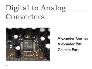
Digital to Analog Converters (DAC)
580 likes | 1.8k Vues
Digital to Analog Converters (DAC). Outline. Purpose Performance Characteristics Types Applications. Purpose. To convert digital values to analog voltages Performs inverse operation of the Analog-to-Digital Converter (ADC). Basic Block diagram of DAC. Analog output voltage Vo.

Digital to Analog Converters (DAC)
E N D
Presentation Transcript
Outline • Purpose • Performance Characteristics • Types • Applications
Purpose • To convert digital values to analog voltages • Performs inverse operation of the Analog-to-Digital Converter (ADC)
Basic Block diagram of DAC Analog output voltage Vo Resistive network Voltage reference Vr I to V converter Digitally controlled switches MSB LSB
General DAC Characteristics • Resolution • Linearity • Accuracy • Speed • Settling Time • Temperature sensitivity • Reference Voltages ME6405 - DAC Lecture
Resolution • The variation of the output voltage corresponding to the variation of the least significant binary bit (LSB)
Linearity • The relation between the digital input and analog output should be linear
Accuracy It indicates how close the analog output voltage is to its theoretical value. Accuracy depends upon the accuracy of the resistors used
Speed • Rate of conversion of a single digital signal to its analog equivalent • Depends on: • Clock speed of input signal • Settling time of DAC
Settling Time Theoretically the analog output voltage should change instantaneously in response to the change in its digital input. but practically it does not change instantaneously. Due to resistors and op-amp, oscillations are observed
Reference Voltages • Non multiplier DAC: Vref is fixed—given by the Manufacturer • Multiplier DAC: Vref can be variable • Multiplies digital word by analog Vref input
Temperature sensitivity The analog output should not change due to the change in the temperature. but practically analog output is the function of the temperature.
Full Scale Voltage • Full scale voltage is determined using the reference voltage ME6405 - DAC Lecture
Types of DACs • Types • Binary Weighted Resistor • R-2R Ladder
Binary Weighted Resistor • Result: • Bi = Value of Bit i
Errors Linearity error offset
Advantages and disadvantages Advantages:- • Easily understood Disadvantages:- • Limited to ~ 8 bits • Large number of resistors • Susceptible to noise • Expensive • Greater Error
R-2R Ladder VREF MSB LSB
R-2R Ladder • Same input switch setup as Binary Weighted Resistor DAC • All bits pass through resistance of 2R VREF MSB LSB
R-2R Ladder • The less significant the bit, the more resistors the signal muss pass through before reaching the op-amp • The current is divided by a factor of 2 at each node LSB MSB
R-2R Ladder • The current is divided by a factor of 2 at each node • Analysis for current from (001)2 shown below R R R 2R 2R R 2R 2R Op-Amp input “Ground” B2 VREF B1 B0
R-2R Ladder • Result: • Bi = Value of Bit i Rf
R-2R Ladder • If Rf = 6R, VOUT is same as Binary Weighted: • Bi = Value of Bit i
2R R R R R 2R 2R 2R Op-Amp input “Ground” VREF VREF B2 B0 R-2R Ladder • Example: • Input = (101)2 • VREF = 10 V • R = 2 Ω • Rf = 2R
Advantages and disadvantages Advantages:- • Only 2 resistor values • Easier implementation • Easier to manufacture • Faster response time Disadvantages:- • More confusing analysis
Digital to Analog Converters -Common Applications • Generic use • Circuit Components • Digital Audio • Function Generators/Oscilloscopes • Motor Controllers
Digital to Analog Converters-Common Applications-Generic • Used when a continuous analog signal is required. • Signal from DAC can be smoothed by a Low pass filter Piece-wise Continuous Output Analog Continuous Output Digital Input n bit DAC 0 bit 011010010101010100101 101010101011111100101 000010101010111110011 010101010101010101010 111010101011110011000 100101010101010001111 Filter nth bit
Digital to Analog Converters-Common Applications-Circuit Components • Voltage controlled Amplifier • digital input, External Reference Voltage as control • Digitally operated attenuator • External Reference Voltage as input, digital control • Programmable Filters • Digitally controlled cutoff frequencies
Digital to Analog Converters-Common Applications-Digital Audio • CD Players • MP3 Players • Digital Telephone/Answering Machines 1 2 3 1. http://electronics.howstuffworks.com/cd.htm 2. http://accessories.us.dell.com/sna/sna.aspx?c=us&cs=19&l=en&s=dhs&~topic=odg_dj 3. http://www.toshiba.com/taistsd/pages/prd_dtc_digphones.html
Digital Oscilloscopes Digital Input Analog Ouput Signal Generators Sine wave generation Square wave generation Triangle wave generation Random noise generation Digital to Analog Converters-Common Applications-Function Generators 1 2 1. http://www.electrorent.com/products/search/General_Purpose_Oscilloscopes.html 2. http://www.bkprecision.com/power_supplies_supply_generators.htm
Digital to Analog Converters-Common Applications-Motor Controllers • Cruise Control • Valve Control • Motor Control 1 2 3 1. http://auto.howstuffworks.com/cruise-control.htm 2. http://www.emersonprocess.com/fisher/products/fieldvue/dvc/ 3. http://www.thermionics.com/smc.htm