Download
1 / 25
250 likes | 460 Vues
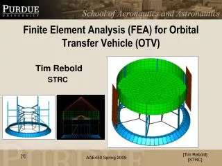
Finite Element Analysis (FEA) for Orbital Transfer Vehicle (OTV). Tim Rebold STRC. [1] . Boundary Conditions (BC’s). z. 8 holes on Payload Attach Fitting (PAF) equally spaced around Spacecraft attached by bolting into launch vehicle interface

E N D
Finite Element Analysis (FEA) for Orbital Transfer Vehicle (OTV) Tim Rebold STRC [1] [Tim Rebold] [STRC]
Boundary Conditions (BC’s) z • 8 holes on Payload Attach Fitting (PAF) equally spaced around • Spacecraft attached by bolting into launch vehicle interface • Bolt acts as a clamped boundary condition x Clamped BC y All 6 degrees of freedom constrained [Tim Rebold] [STRC] [2]
Applied Loads - Dnepr Payload Requirements Notes: Lateral accelerations may act in any direction, simultaneously with longitudinal ones 2. Dynamic accelerations are preceded by “±” symbol Tables based from Dnepr User’s Guide [Tim Rebold] [STRC] [3]
System Representations • Lander • Propulsion System • E-MOD System • Systems represented by placing lumped mass elements at the center of mass of that system • These elements have the same mass & inertia properties [Tim Rebold] [STRC] [4]
FEA Analysis • Von Mises Stress observed • Material allowables based on Aluminum 6061-T6 yield strength • Margin of Safety (MS) reported and documented for all major systems and components [Tim Rebold] [STRC] [5]
Skirt Analysis – Set Up (100 grams) Lander The skirt joins the larger 1.8 m diameter OTV to the smaller 1.3 m diameter Lander Clamped boundary conditions representing bolted hole interface [Tim Rebold] [STRC] [6]
Skirt Analysis – Peak Stress 64.3 N/mm2 Peak Stress σ = 70 N/mm2 σY = 270 N/mm2 MS = 2.86 69.6 N/mm2 [Tim Rebold] [STRC] [7]
Skirt Analysis - Peak Displacement = 0.5 mm, Buckling Load Factor = 2.21 [Tim Rebold] [STRC] [8]
Skirt Analysis (100 grams) - Observations • Stress is not a concern • Buckling of thin sheet webs will determine sizing of skirt • As a result of reducing mass, the modal frequencies will decrease which is an adverse effect [Tim Rebold] [STRC] [9]
OTV Analysis100 grams [Tim Rebold] [STRC] [10]
Propulsion Frame - Stress Accelerations Yield Peak Stress σ = 324 N/mm2 σY = 270 N/mm2 MS = -0.17 [Tim Rebold] [STRC] [11]
Buckling Buckling load Factor = 0.19 Buckling [Tim Rebold] [STRC] [12]
FEA – Summary Observations • Yielding in propulsion frame member 4 due to lateral acceleration applied in that member’s direction • Displacement in E-MOD floor skin relatively high, but stresses are low and displacement does not interfere with anything in the surroundings • E-MOD floor supports are stronger than necessary • Buckling in C-Channels • Lateral mode too low Design Changes • Increase cross section of member 4 of propulsion frame, and connect propulsion components to more structural members • Decrease cross-sectional dimensions of E-MOD floor beams • Increase cross section dimensions of C-Channels until buckling occurs at a higher load 4 2 3 1 [Tim Rebold] [STRC] [13]
OTV Final Analysis100 grams [Tim Rebold] [STRC] [14]
Propulsion Frame - Stress Accelerations Peak displacement is 2.19 mm Peak Stress σ = 80 N/mm2 σY = 270 N/mm2 MS = 2.38 [Tim Rebold] [STRC] [15]
E-MOD - Stress Peak Stress σ = 72 N/mm2 σY = 270 N/mm2 MS =2.75 Peak displacement remains at 40 cm [Tim Rebold] [STRC] [16]
E-MOD floor support - Stress Peak displacement is 3.62 mm and occurs at ring interface Peak Stress σ = 92 N/mm2 σY = 270 N/mm2 MS = 1.93 [Tim Rebold] [STRC] [17]
OTV Frame – Peak Stress in OTV Peak stress occurs at a joint where a C-Channel and E-MOD floor support beam meet Peak Stress σ = 92 N/mm2 σY = 270 N/mm2 MS = 1.93 [Tim Rebold] [STRC] [18]
Buckling Load Factor is 1.42 [Tim Rebold] [STRC] [19]
Modes – Lateral mode at 10.6 Hz Axial mode is not a concern [Tim Rebold] [STRC] [20]
FEA Analysis - Conclusions • Stiffness and buckling were driving factors in determining size • Members act together effectively to limit peak stresses and displacements • Low stresses ensure welds and other connection methods will meet strength criteria [Tim Rebold] [STRC] [21]
FEA Analysis Breakdown – 100 g [Tim Rebold] [STRC] [22]
Structural Budget – 100 g *Estimates [Tim Rebold] [STRC] [23]
FEA Analysis Breakdown – 10 kg [Tim Rebold] [STRC] [24]
Structural Budget – 10 kg *Estimates [Tim Rebold] [STRC] [25]