Download
1 / 42
420 likes | 578 Vues
THEMIS MISSION PRE-SHIP REVIEW Thermal Christopher Smith University of California - Berkeley. Thermal Hardware Status Update. Thermal Hardware Status Update. Thermal Modeling Status. Second Model Correlation Complete All boxes within 5 degrees of test temperatures

E N D
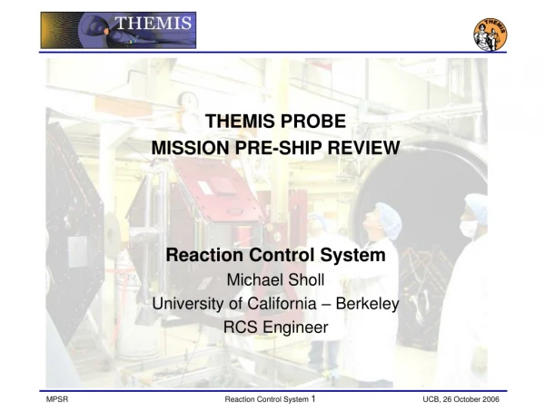
THEMIS MISSION • PRE-SHIP REVIEW • Thermal • Christopher Smith • University of California - Berkeley
Thermal Modeling Status • Second Model Correlation Complete • All boxes within 5 degrees of test temperatures • Thermostat set points verified … except: • IDPU and BAU Primary and Secondary • IRU Primary and Secondary was verified on P5 only • Heater duty cycles less than 70% • Flight Predicts for launch case are complete • The remainder are currently running
PFRs and RFAs • Five PFRs closed since PER • PFR-186: Thermal Blanket Velcro Adhesion Failure • PFR-205: Fuel Line Zone #1 Secondary Thermostat to Low • PFR-215: F3 XPNDR Secondary Setpoints the Same as Primary • PFR-225: F3 MSSS Primary and Secondary service switched • PFR-226: P1 Thermistors BTMPRCSLN1 and BTMPRCSSVC swapped • RFAs • P3_PSR_4: Periodic Emissivity Measurements, closed • P1_PSR_2: Transponder Radiator Resizing, submitted • P1_PSR_3: Test Versus Flight Radiator Heat Flow Comparison, closed • P1_PSR_4: Comparison of Pre-test Flight Predicts to Correlated Model, submitted
Test Facilities • Testing took place in JPL chamber #7 • 74”x134” • Simultaneously accommodated two Themis probes for testing with chamber divider shroud • Gaseous or liquid nitrogen controlled shrouds • GN2: –130 to +125 deg C • LN2: -175 deg C • Two TQCMs • Nitrogen Vent-back is rate limited • 30 power Supplies • 168 Type T thermocouple feedthroughs • 250 Channel DAQ system • 1000 L/sec Leybold and 2000 L/sec Balser Turbo pumps • Tank cleanliness certified prior to T-V test
Test Heaters • 12 test heaters provided for each thermal box • 1 heater for the Antenna Hat Coupler • 1 Heater for the Separation Ring • 1 heater for controlling the beam warm up
Instrumentation • 168 T-type thermocouples used on P2 • 80 T-type thermocouples used on P1, P3-5 • 64x2 used on the spacecraft • 16x2 used for heaters and environment • Transponder fully instrumented • Added thermocouples to the RCS system on P3
Other Changes • Increased transponder radiator size by 30% to match hardware modifications • Heater power applied as a function of bus voltage • Added heat leak from sun sensor to thermal box corner panel • Ran two separate cold balance cases to account for different top plate temperatures in actual test • Moved several Thermostat node locations to better reflect as installation photographs • Added Thermostat masses on RCS Fuel Lines Heater Zones (12 grams per TSTAT) • Removed Line 1 heater service from service valve TSTAT node
Anomalies During Test • TVAC 1 • PFR-205, Closed: Fuel Line Zone #1 Secondary Thermostat to Low • Heat leak to bottom deck caused TSTAT to appear to be tripping at a low temperature when it was functioning normally. However this exposed a real cold spot in the RCS fuel line 1. Fly As Is. Only presents a problem in long eclipses when the primary heater service has also failed. • TVAC 2 and 3 • PFR-215, Closed: F3 Transponder Secondary Setpoints the Same as Primary • Fly As Is • PFR-225, Closed: F3 MSSS Primary and Secondary service switched • Fly As Is • PFR-226, Closed: P1 Thermistors BTMPRCSLN1 and BTMPRCSSVC swapped • Database Updated to swap mnemonics
THERMAL • BACKUP SLIDES
Thermal Testing History • Thermal Testing History
Individual Instrument TVAC (2 Cycles) Probe Level TVAC (4 Cycles, 3 Balance Points) Thermal Cycle Accumulation Instrument Suite TVAC (6 Cycles) Individual Probe Component TVAC (8 Cycles)
Thermal Vac Testing History Instruments
Thermal Vac Testing History Instruments
Thermal Vac Testing History Suite and IDPU
Thermal Vac Testing History Mag Booms
Thermal Vac Testing History Probe Components
Post TVAC 1 • Correlation Changes and Data
P2 TVAC Results Before Correlation • Comparison of the test data with test predicts show most components are within 5°C of test predicts for Hot and Cold Balance Cases • The Survival Balance Case (Cold 2) results indicate that the model is conservative on the cold side which means that flight heater powers will be less than predicted.
Other Changes • Added Thermostat masses on RCS Fuel Lines Heater Zones (12 grams per TSTAT) • RCS Max Heater Power multiplied by 1.375 (Accounts for 33V Bus instead of 24V) • Adjusted RCS Latch Valve, P-Ducer and Solenoid Valve MCp values to account for single node model (FAC 0.2). • Adjusted Sun Sensor outer face emissivity from 0.2 to 0.8 (accounts for black anodized Baffles)