Download
1 / 49
490 likes | 728 Vues
Accidental beam losses and protection in the LHC. R.Schmidt and J.Wenninger f or the Working Group on Machine Protection HB 2004 Bensheim. LHC parameters and associated risks Overview accidental beam losses Aperture and accidental beam losses Protection and redundancy Conclusions.

E N D
Accidental beam losses and protection in the LHC R.Schmidt and J.Wenninger for the Working Group on Machine Protection HB 2004 Bensheim LHC parameters and associated risks Overview accidental beam losses Aperture and accidental beam losses Protection and redundancy Conclusions HB 2004
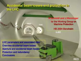
Beam dump tunnel LHC tunnel HB 2004
Momentum at collision 7 TeV/c Beam intensity 2808 1.1 1011 protons per beam Luminosity 1034 cm-2s-1 Dipole field at 7 TeV 8.33 Tesla Typical beam size 200-300 µm Energy stored in the magnet system: 10 GJoule Energy stored in one (of 8) dipole circuit: 1.1 GJoule Energy stored in one beam: 350 MJoule Average beam power to compare with high power accelerators, both beams: some 10 kWatt Instantaneous beam power for one beam: 3.9 TWatt ….during 89 µs ….corresponds to the power of 1700 nuclear power plants Energy to heat and melt one kg of copper: 700 kJ Some numbers for 7 TeV HB 2004
Intensity one “pilot” bunch 5109 Nominal bunch intensity 1.11011 Batch from SPS (216/288 bunches at 450 GeV) 31013 Nominal beam intensity with 2808 bunches 31014 Damage level for fast losses at 450 GeV 1-21012 Damage level for fast losses at 7 TeV 1-21010 Quench level for fast losses at 450 GeV 2-3109 Quench level for fast losses at 7 TeV 1-2106 Damage and quench assessment approximative, supported by experience in SPS and calculations Further calculations and material tests at SPS in two weeks planned Bunch intensities, quench and damage level HB 2004
Failure scenarios and accidental beam losses A large number of different mechanisms can cause accidental particle losses: Classification of accidental beam losses according to time constant for the loss • Ultra fast beam losses (single turn or less) • to be avoided, beam dump block is the only element that can safely absorb the 7 TeV LHC beam passive protection with collimators and beam absorber • Very fast beam losses (some turns to some milliseconds) • Fast beam losses (5 ms – several seconds) • Slow beam losses (several seconds – 0.2 hours) active protection, by detecting failure and extracting the beams into beam dump block HB 2004
Single turn accidental beam losses Failure mechanisms • Failure of beam dump kicker (prefiring, asynchronous beam dump) • Failure of kickers for tune measurements and aperture exploration • During transfer and injection • failure of injection kicker • wrong trajectory or mismatch of beam energy • obstruction of beam passage • Recent studies on protection during transfer and injection of the beams from SPS at 450 GeV to the LHC (see H.Burkhardt) Strategy for protection • Avoid such failures (systems with high reliability) • Block beam transfer from SPS to LHC if parameters are not correct (i.e. magnet current) • Beam trajectory after such failure is reasonably well defined • Passive protection: rely on collimators and beam absorbers HB 2004
Consequence of a failure scenario: Full 7 TeV LHC beam deflected into copper target 2808 bunches 7 TeV 350 MJoule Copper target 2 m Energy density [GeV/cm3] on target axis vaporisation melting Target length [cm] collaboration with N.Tahir (GSI) et al. HB 2004
Density change in target after impact of 100 bunches Copper target copper solid state radial 100 bunches – target density reduced to 10% collaboration with N.Tahir (GSI) et al. Target radial coordinate [cm] • Energy deposition calculations using FLUKA • Numerical simulations of the hydrodynamic and thermodynamic response of the • target with two-dimensional hydrodynamic computer code • From this calculations one can estimate the longitudinal range of full beam in copper between 10m and 40m HB 2004
LHC Layout eight arcs (sectors with a length of about 2300 m) eight long straight sections (about 700 m long) IR5:CMS IR6: Beam dumping system IR4: RF + Beam instrumentation IR3: Momentum Cleaning (normal conducting magnets) IR7: Betatron Cleaning (normal conducting magnets) IR8: LHC-B IR2:ALICE IR1: ATLAS Injection Injection Transfer Line Transfer Line HB 2004
Collimators for cleaning the beam halo • close to the beam between 5-10 • must be accurately adjusted (within a fraction of one ) • position depends on optics and possibly on energy IR5:CMS IR6: Beam dumping system IR4: RF + Beam instrumentation IR3: Momentum Cleaning (normal conducting magnets) IR7: Betatron Cleaning (normal conducting magnets) IR8: LHC-B IR2:ALICE IR1: ATLAS Injection Injection Transfer Line Transfer Line HB 2004
Collimators for protection of equipment against single turn beam losses • shadow equipment downstream • must be adjusted (better than one σ) • position depends on LHC operational mode (injection, energy ramp, …) and on optics IR5:CMS IR6: Beam dumping system IR4: RF + Beam instrumentation IR3: Momentum Cleaning (normal conducting magnets) IR7: Betatron Cleaning (normal conducting magnets) IR8: LHC-B IR2:ALICE IR1: ATLAS Injection Injection Transfer Line Transfer Line HB 2004
For protection of equipment against multiturn beam losses • all collimators limiting the aperture contribute to this function IR5:CMS IR6: Beam dumping system IR4: RF + Beam instrumentation IR3: Momentum Cleaning (normal conducting magnets) IR7: Betatron Cleaning (normal conducting magnets) IR8: LHC-B IR2:ALICE IR1: ATLAS Injection Injection Transfer Line Transfer Line HB 2004
Collimators for protection and cleaning of the low-beta insertions, mainly in IR1 and IR5 • close to the beam about 10 • must be accurately adjusted (within about one ) • mainly required during squeeze and for squeezed beams IR5:CMS IR6: Beam dumping system IR4: RF + Beam instrumentation IR3: Momentum Cleaning (normal conducting magnets) IR7: Betatron Cleaning (normal conducting magnets) IR8: LHC-B IR2:ALICE IR1: ATLAS Injection Injection Transfer Line Transfer Line HB 2004
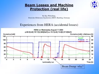
Lifetime of the beam - for nominal intensity at 7 TeV Accidental beam losses HB 2004
Closed orbit grows around the ring Fast emittance growth: beam size explodes Both Can happen very fast Can be detected around the entire accelerator Local orbit bump cannot happen very fast might be detected only locally Protection: Detect failure and dump beam Detection, transmission to beam dump, and beam dump – takes at least 3 turns ~ 270 s Accidental multiturn beam losses HB 2004
Multiple turn failures: Magnet powering failures • Quench of superconducting magnets • Discharge of superconducting magnets switching a resistance into the circuit (after quench, or by accident) • Failure of magnet powering For some magnets very fast beam loss (several turns): D1 normal conducting magnet • Electric short in the coil of a normal conducting magnet HB 2004
Multiple turn failures: Other failures • Aperture limitation in beam pipe (circulating beam) • Vacuum valve moves into beam • Collimator moves into beam • Other element moves into beam • Loss of beam vacuum • Failure in the RF system • Debunching of beam and number of protons in the abort gap… could lead to single turn failure when beam is dumped • Operational failures • Combined failures, for example after Mains Disturbances (thunderstorm, …) HB 2004
Beam losses and aperture The aperture of the LHC at 450 GeV is limited (about 7.5σ, assuming closed orbit excursions=4 mm, beta-beating, ….) Critical operation at 7 TeV with squeezed optics: • -function up to 4850 m in insertions IR1 and IR5 • very strong low- quadrupole magnets with orbit offset • normal conducting dipole magnets • superconducting dipole magnets • In general, particle losses first at collimators • Fast orbit changes are the most critical failures • collimators at about 6-9 from the beam • 1% of the beam would damage the collimators for fast beam loss HB 2004
Critical apertures around the LHC (illustration drawing)in units of beam size at 450 TeV collimators (momentum cleaning) collimators (betatron cleaning) arc aperture down to about 7.5 6-9 aperture in cleaning insertions about 6-9 aperture in cleaning insertions about 6-9 IR1 IR2 IR3 IR4 IR5 IR6 IR7 IR8 HB 2004
Critical apertures around the LHC (illustration drawing)in units of beam size TCT collimators (momentum cleaning) TCT TCDQ at ~10 collimators (betatron cleaning) beam dump partial kick 6-9 aperture in cleaning insertions about 6-9 7 TeV and * = 0.55 m in IR1 and IR5 Triplet Triplet triplet aperture about 14 arc aperture about 50 IR1 IR2 IR3 IR4 IR5 IR6 IR7 IR8 HB 2004
Most likely failures for fast losses: quenchesFailures leading to the fastest multiturn losses: D1 magnet orbit [mm] MB quench fast loss Quench of: - MQX - D2 - MB Powering Failure of D1 normal conducting D1 normalconducting very fast loss D2 quench fast loss MQX: 2 quads quench fast loss time [seconds] V.Kain Diploma thesis 2001 / O.Brüning Squeezed optics with max beta of 4.8 km All 4 quadrupole magnets (inner triplet MQX) quench , approximately Gaussian current decay with time constant 0.2 s Powering failure for D1, exponential current decay, time constant 2.5 s Quench of one MB, approximately Gaussian current decay with time constant 0.2 s HB 2004
Particles that touch collimator after failure of normal conducting D1 magnets After about 13 turns 3·109 protons touch collimator, about 6 turns later 1011 protons touch collimator 1011 protons at collimator “Dump beam” level V.Kain HERA experience confirmes worries: very fast beam losses HB 2004
Protection and redundancy: what triggers a beam dump? • Hardware diagnostics • Quench signal from Quench Protection System • Beam loss monitors at the collimators and other aperture limitations • Beam loss monitors in the arcs • Magnet current change monitors • Beam position change monitors • Fast beam current decay (“lifetime”) monitors HB 2004
Hardware failure diagnostics • Vacuum valve leaving the “OUT” position (…away from end switch) • Other movable devices leaving the “OUT” position • Powering failures detected by the power converter, requesting a beam dump (typical times in the order of 10 ms) • Failures of cooling for normal conducting magnets • Failure in the RF system • Anticipated failure in the beam dumping system (before it is too late), e.g. when 1 out of 15 kicker is lost • Failure in critical beam absorbers and collimators HB 2004
Hardware failure diagnostics PLUS • Does not require collimators to have correct settings • If early enough, can dump the beam before particle losses MINUS • For many type of failures the beam dump comes too late • Complexity of hardware: not all failures are detected • Too many channels: too many “False Beam Dumps” • Risk of including failures that would not lead to particle losses HB 2004
Quench detection • Magnet starts to quench • Resistive Voltage across magnet > 0.1 V • +10 ms: quench detection • fire quench heater • requests energy extraction • requests a beam dump The quench heaters become effective + 3 ms: the interlock system transmits the request to the beam dump +300 s: the beam dump kicker extracts beam Magnet current starts to debypass magnet by diode +5 ms: current starts to decay exponentially HB 2004
Quench detection PLUS • Does not require collimators to have correct settings • If early enough, beam gone before losses • Dumps beam for failures of the quench protection system • Does not reduce the availability of LHC: Quench protection is always required. After a quench the beam must be dumped MINUS • Only covers beam losses due to magnet quenches • Might be too late (…being further analysed, efficiency depends on quench process, magnet field, beam loss pattern, etc…) • Large complexity (several 1000 channels) – good post mortem analysis required HB 2004
Beam loss monitoring at aperture limitations In general, collimators are limiting the aperture Always true for beam blow up Mostly true for orbit changes Beam loss monitors at aperture restrictions continuously measuring beam losses Losses are detected within less than a turn After detection it takes 2-3 turns to extract all particles into beam dump block HB 2004
Beam loss monitoring at aperture limitations PLUS • Should capture (nearly) all types of accidental beam losses • Dumps the beam if there are really particle losses • Very fast (< 100 s) • Limited complexity (some 100 channels) • Expected to be very reliable MINUS • Does require collimators to have correct settings and defining the aperture • Does not catch beam losses in the arcs (for example, closed orbit bumps) • Random spikes might trigger beam dump • Setting of thresholds not obvious - if too low, False Beam Dumps – if too high - risk of damage HB 2004
Beam loss monitoring around the accelerator Beam loss monitors continuously measuring beam losses Together with the BLMs at aperture limitations, covers most of the LHC (all arcs) Losses can be detected within less than a turn After detection it takes 2-3 turns to extract all particles into beam dump block HB 2004
Beam loss monitoring around the accelerator PLUS • Dumps the beam if there are really particle losses • For failures leading to orbit changes and emittance growth • Detection can be made very fast (< 100 s) • Does not require collimators to have correct settings • Catches failures that appear only in the arcs (for example, closed bump) MINUS • Large complexity (some 1000 channels) • Could increase number of False Beam Dumps • Setting thresholds: delicate balance between avoiding magnet quenches and avoiding False Beam Dumps HB 2004
Magnet current decay monitoring for critical magnets Very fast detection of power converter / magnet failures • Monitors change of magnet current (Hall probes, voltage, …) • Prototype “quick and dirty” gave promising results (M.Zerlauth) • Similar technique recently successfully implemented at HERA (M.Werner) • Should be possible to detect powering failures in less than one millisecond HB 2004
Magnet current decay monitoring for critical magnets PLUS • Independent method to monitor failures in the powering system: power converter fault / thunderstorm / short circuit in magnet / other problems • Does not require collimators to have correct settings • Can be made fast (< 1ms) • Mainly for normal conducting magnets MINUS • Needs to be demonstrated if practical (EMC, …) – wait for HERA experience • Setting of thresholds required – could be delicate • Should be limited to a few electrical circuits with normal conducting magnets – otherwise too complex HB 2004
Beam position change monitors If the orbit start to moves very fast, dump the beam • Fast orbit changes can be observed anywhere around the LHC • Observation for each beam, each plane, two monitors with 90 degrees phase advance: in total 8 BPMs • …system with limited complexity • BPMs at location of high beta function, using the same monitors that are already required for machine protection (to ensure x < 4 mm in the insertion IR6 for the beam dumping system) HB 2004
Beam position change monitors: thresholds 450 GeV: fastest orbit movement during normal operation by an orbit corrector magnet Superconducting orbit correctors : 2 mm/s … 15 mm/s Normal conducting orbit correctors: 0.6 mm/s … 1.7 mm/s 450 GeV: if the change of the orbit exceeds, say, some 10 mm/s corresponding to 0.01 mm/msec, there is something wrong Detection of very fast orbit drifts: (IF dx/dt > 0.1 mm/ms) OR (IF dx/dt > 1 mm/100ms) THEN beam dump 7 TeV: if the change of the orbit exceeds, say, some 1 mm/s corresponding to 0.001 mm/msec, there is something wrong (IF dx/dt > 0.05 mm/ms) OR (IF dx/dt > 0.3 mm/100ms) THEN beam dump numbers preliminary HB 2004
Beam position change monitors PLUS • Independent method to measure fast orbit drifts due to failures • Does not require collimators to have correct settings • Can be made fast (< 1ms) • Beam dump before particles are lost • Limited complexity MINUS • Is it practical ? False Beam Dumps ? • Setting of thresholds delicate • What to do during injection, during kicks for Q-measurements, … to be studied • Only for beam orbit changes, not for emittance growth • Studies needed HB 2004
Fast beam current decay monitoring Very fast beam current monitor, could detect losses within short time • Measuring proton losses with, say, N / t = 1010 protons • Interlock condition • if (N / t > Nthreshold(E) · 1010) THEN BEAM DUMP • t could be as short as one turn • Nthreshold decreases with energy to be always efficient • For start of LHC operation, when intensity is limited, resolution should be no problem • Challenge: must be fastand accurate • First discussions with experts - looks promising HB 2004
Fast beam current decay monitoring PLUS • Independent method to measure beam losses • Does not require collimators to have correct settings • Fast for reduced accuracy (< 1ms) • Slow for high accuracy (> 10ms) • Limited complexity – one instrument MINUS • Needs to be demonstrated if practical • Setting of thresholds required • Not sufficient for all LHC operation modes and for shortest accidental beam losses time constants • Could be ok for 450 GeV, not for 7 TeV • Studies needed HB 2004
Conclusions Protection for LHC starts before extraction from SPS Protection is required during the entire cycle Large redundancy in protection Availability of the machine due to the complex protection is an important issue Large energy: stringent protection required - too few interlocks could lead to severe damage of the LHC Unprecedented complexity: too conservative interlocking of the machine protection systems could prevent efficient LHC exploitation Initial operation with part of the protection systems Commissioning of other protection systems during initial operation HB 2004
Some questions to the workshop…….. Fast beam current decay monitoring Fast beam position change monitoring What can be achieved? Who has experience? Where else might such systems be required? HB 2004
The presentation is based on the work that was performed in many groups in several CERN Departments, as well as collaborators from other labs (Fermilab, GSI, Protvino, Triumf, ….) Contributions of many colleagues are acknowledged, in particular for the discussions in the Machine Protection WG, Collimation WG and Injection WG particular thanks for R.Assmann, H.Burkhardt, E.Carlier, B.Dehning, B.Goddard, E.B.Holzer, J.B.Jeanneret, V.Kain, B.Puccio, J.Uythoven. M.Zerlauth …… Acknowledgements HB 2004
Recent question in MPWG: Can we dump the beam in time after a quench of a dipole magnet? • Beam is to be dumped before the current in the dipoles starts to decay • The sequence of following actions has to be determined • beam loss causes the magnet to quench • the voltage builds up and exceeds the threshold of the quench detector • the quench detector detects the voltage after some time • the quench detector fires quench heaters or triggers the energy extraction • at the same time, the PIC is informed • PIC sends a dump request to the BIC • the heaters become efficient • the BIC sends a dump request to the beam dumping system • the voltage exceeds the diode voltage, and the current starts to bypass the magnet • the switch opens, and the current in the string of magnets decays • The Powering Interlock Controller is the only system sending (direct) beam dump request after powering failures • ‘Secondary’ protection with collimators, BLM (possibly BPM / beam lifetime) Defined sequence Who’s quickest? HB 2004
Hardware configuration (main dipole circuit) and signal transmission ‘Quench Loop’ stretching over the arcs Beam Dump Request Beam Interlock Controller Beam Dump Request Beam Dumping System Quenching (dipole) magnet in the arc HB 2004
The PIC process times • Interlock Controller is based on a PLC controlled process, monitoring and controlling up to 45 electrical circuits (>200 signals) • For time (beam) critical circuits -> configurable hardwired matrix in parallel PIC Controller (PLC) Process time < 5ms Power Converters Power Permit, Powering Failure, Discharge Requests Quench Protection System Quench Signals, Discharge Requests For main circuits Hardware Matrix (CPLD) Process time < 0.2ms Beam Dump Requests HB 2004
The Timescales Decay starts somewhat before the complete arc extinction due to resistive arc // resistor Diode becomes conductive > 80ms Current in dipole circuit < 15 μs < 100 μs 5..7 ms T1 EE system reads Quench signal Mechanic opening & arc extinction T3 Last branch open, arc is extinct – Current in dipole magnets decays T2 Switch Opening < 100μs 0.2 … 5ms < 270μs < 15 μs < 100 μs PIC process T2 PIC reads signal T3 PIC issues beam dump T5 Completion of beam dump T0 Quench signal T4 Beam dump is received by the BIC T1 Quench Loop Controller Receives signal HB 2004
Conclusions • Due to the delay in the switch opening of the 13kA energy extraction system, the beam is dumped before the current in the magnet starts decaying • also true in case of self triggering of EE • For all other sc magnets the time constraints are less critical • For time critical signals (mainly main dipole and quadrupole circuits due to large effects on the circulating beams), a hardwired matrix within the PIC can be configured in parallel to the PLC process • What to do for nc magnets?! HB 2004