Download
1 / 36
440 likes | 850 Vues
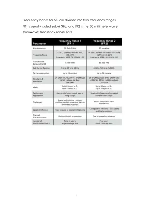
RF Front End Radio Design- Simulations and Specifications. Hemish Parikh Advisor: Prof. William R. Michalson. RF Front End Receiver Design - Outline. Outline. Overview System parameters Specifications System Analysis System Parameter relations System Simulations in ADS Roadmap

E N D
RF Front End Radio Design-Simulations and Specifications Hemish Parikh Advisor: Prof. William R. Michalson
RF Front End Receiver Design - Outline Outline • Overview • System parameters • Specifications • System Analysis • System Parameter relations • System Simulations in ADS • Roadmap • Questions
You are Here RF Front End Receiver Design - Overview Overview
Model 1: Direct RF Sampling Model 2: Direct Down Conversion Today’s Focus RF Front End Receiver Design - Overview Possible Front End Models
RF Front End Receiver Design – System Parameters System Parameters • System Gain (G) • System Noise Figure (NF) • Input 3rd Order Intercept Point (IIP3) • Receiver Sensitivity (Rx-Sens) • Receiver Spurious Free Dynamic Range (SFDR) • Inter Modulation Distortion (IMD)
RF Front End Receiver Design - Specifications Component Identification RF MICRO DEVICES RF-2361 ANALOG DEVICES AD-8367 COMTELCO PEXW-400 ANALOG DEVICES AD-8343 MURATA 415-465 MHz MURATA 0-50 MHz VARI-L VCO190-445T VECTRON OSC-1B0-10MHz ANALOG DEVICES ADF-4112
RF Front End Receiver Design - Specifications Specifications - LNA • RFMD – 2361 • Low Noise Figure (NF): 1.9 dB • Gain (G): 20 dB • Input 3rd order intercept point (IIP3): 6 dBm • Max input RF level: +10 dBm
RF Front End Receiver Design - Specifications Specifications - AGC • AD 8367: • Variable Gain: -2.5 dB to 42.5 dB • NF ??? • IIP3 ???
LO+RF LO-RF RF LO IM Products RF Front End Receiver Design - Specifications Specifications – Mixer (1) • Big role in overall system performance • Mixing is just frequency shifting • Produces LO+RF and LO-RF • Produces Unwanted Inter Modulation Distortion (IMD) • IM products: (M*LO + N*RF) and (M*LO - N*RF) • Good Mixer or a Bad Mixer !!!!!????
RF Front End Receiver Design - Specifications Specifications – Mixer (2) Good Mixer Low Noise Figure (< 15dB) High IP3 ( > 15dB) Good Port Isolation (~ 50dBm) High Conversion Gain LO drive level (application dependent)
RF Front End Receiver Design - Specifications Specifications – Mixer (3) • AD 8343: • NF: 11 dB • Gain: 7.1 dB • IIP3: 20 dBm • LO drive level: -10 dBm
RF Front End Receiver Design - Specifications Specifications – Mixer (4) LO = 400 MHz
Vectron TCXO: Frequency: 10 MHz Stability: 2.5 ppm Mechanical Trip: +/- 3 ppm Vari-L VCO: Tuning Range: 400 to 500 MHz Tuning Sensitivity: 15MHz/V RF Front End Receiver Design - Specifications Specifications - TCXO / VCO
RF Front End Receiver Design - Specifications Specifications – PLL (1) • ADF 4113: • Programmable counters: P, B, A, R
RF Front End Receiver Design – Analysis System Gain G1= -2dB G2= 20dB G3= 7.1dB G4= -2dB G(dB) = G1+G2+G3+G4 P_in = G + P_out
Noise Figure quantifies how noisy the system is Reference Max allowed NF: WCDMA: 9 dB Cellular: 10 dB PCS: 6.8 dB Noise Figure is Noise Factor in dB System noisy due to losses in circuit, solid state devices. GOAL: Design receiver with lowest NF !!!!!! RF Front End Receiver Design – Analysis System Noise Figure (1) Noise Sources System Noise Thermal Noise
Noise Figure of Cascaded System RF Front End Receiver Design – Analysis System Noise Figure (2) Critical G1= -2dB G2= 20dB G3= 7.1dB G4= -2dB NF1=2dB NF2=1.9dB NF4=11dB NF5= 2dB
RF Front End Receiver Design – Analysis System Input IP3 (1) Problem: Relatively large magnitude and difficult to filter IP3 is a measure of system linearity. Point where the desired signal and the 3rd order distortion have equal magnitudes. Third Order products:2f1+f2, 2f1-f2, 2f2+f1, 2f2-f1, where f1 and f2 are two inputs. Reference Min allowed IIP3: Cellular: -13 dBm PCS: -11.425 dBm
Critical RF Front End Receiver Design – Analysis System Input IP3 (2) G1= -2dB G2=20dB G3=7.1dB G4= -2dB IIP1= dBm IIP2= 6dBm IIP3=20dBm IIP4= dBm
Rx. Sens = Noise Floor + 10log(BW) + SNR_min + Noise Figure Significantly reduces The Rx. Sens RF Front End Receiver Design – Analysis Receiver Sensitivity (1) • Rx. Sens quantifies the receivers ability to respond to weak signal. A/D Input SNR_min = 12dB (Assume) BW = 50MHz Rx. Sens = -174 + 77 + 12 + 4.22 = -80.78 dBm
RF Front End Receiver Design – Analysis Receiver Sensitivity (2) As BW increases, sensitivity becomes poor
RF Front End Receiver Design – Analysis Receiver Sensitivity (3)
RF Front End Receiver Design – Analysis Receiver Spurious FreeDynamic Range • High DR means Receiver can operate over wide range of input power levels. • Receiver’s Output starts to saturate if the Input is above the range • Below DR, the noise dominates. SFDR = 0.66 (IIP3 – Rx. Sens) = 0.66 (1.1 + 80.78) = 54.6 dB
RF Front End Receiver Design – Analysis AGC Issues • Max AGC Gain: • Lowest NF • Lowest IIP3 • Min AGC Gain: • High IIP3 • High NF • Poor Dynamic Range: 25dB
RF Front End Receiver Design – Parameters Relations System Parameters Relations Higher IP3 Maximize DR Maximize Rx. Sens Application Dependent Minimize NF Bandwidth Dependent
RF Front End Receiver Design - Simulations ADS simulations for Gain (1)
Swapped RF Front End Receiver Design - Simulations ADS simulations for Gain (2)
RF Front End Receiver Design - Simulations ADS simulations for NF(1)
Swapped RF Front End Receiver Design - Simulations ADS simulations for NF(2)
RF Front End Receiver Design - Simulations ADS simulations for IMD (1)
RF Front End Receiver Design - Simulations ADS simulations for IMD (2)
RF Front End Receiver Design - Simulations ADS simulations for IMD (3)
RF Front End Receiver Design - Simulations ADS simulations for SFDR Rx Signal Level = -25dBm SFDR ~= 50 dB SFDR
RF Front End Receiver Design Roadmap • ADS with Matlab • ADS with Instruments • Set-up Evaluation board • Migrate to 2.4 GHz