Download

1 / 52
540 likes | 771 Vues
PLC front-end Design Review. Curtis Mayberry 7-5-11. Revised Project Description. Block Diagram. Stage 2. Stage 1. RTD TC Thermistor +/-10v, +/-5v 4-20mA. Cost-Effective. Signal Conditioning. ADC. Microcontroller. High-Accuracy. Super-Mini Dig Labview. The Plan.

E N D
PLC front-end Design Review Curtis Mayberry 7-5-11
Block Diagram Stage 2 Stage 1 RTD TC Thermistor +/-10v, +/-5v 4-20mA Cost-Effective Signal Conditioning ADC Microcontroller High-Accuracy Super-Mini Dig Labview
The Plan • May 16: First Day • May 21: Project Definition & training (1 week) • June 5 - June 10: FAE conference in Tucson (1 week) • July 5: Block Diagrams, calculations (accuracy), simulations, Part selection & ordering, initial schematic (4 weeks) • July 14: PCB layout (2 weeks) • July 21: Basic LabView Coding & Testing preparation (1 week) • July 29: Initial lab results -Oven(~1 weeks) • August 3: Accuracy tests (Tucson?) • August 5: Final Report (2 days) • August 10: Preliminary Presentation (2 days) • August 12: Final Presentation (2 days) • August 18: Last Day (1 week)
Universal Inputs 0-10v and +/- 10v, 0-5v and +/- 5v, 4-20mA
Universal Voltage Input • 0-5v, 0-10v, +/- 5v and +/- 10v universal voltage input • Change resistance values to change input voltage levels • Second order RC filter with poles at 39 Hz and 3900Hz • Opamp to scale down input • 2.5v reference generated to scale input • Opa2333: Low offset voltage and drift, rail-to-rail input, dual opamp part
Noise Calculations: Voltage Reference • 2.5v Reference • REF5025: 625nVRMS • OPA333: 869 nVRMS • Filter KTC noise: 202.8nVRMS • Reference Output 10kΩ: 202.8 nVRMS • Total Noise: 1.108µVRMS • Current Noise: 26.34nVRMS (negligible)
Noise Calculations • Input Filter • 82nF filter KTC noise: 224 nVRMS • 820pF filter noise: 211.47 nVRMS • Total Noise: 308.5 nVRMS • Amplifier Noise: • Feedback Network (16.67kΩ): 828nVRMS • OPA333 noise: 869.5nVRMS • Total Noise: 1.2µVRMS
Noise Calculations: Total • ADC V+ input noise total: 1.503µVRMS • ADC V- input noise total:1.089uVRMS
Noise Calculations: Bringing it all together • ADC noise: 1.35 µVRMS • Noise at Apga =1 and 5 SPS
Resistor Mismatch Errors (Worse Case) • Resistor Options (worse case) • Set 1: 668.7 µV (0.1% resistors) • Set 2: 3.337 mV (0.1% resistors) • Set 2: 1.668 mV (0.05% resistors) • Set 2:666.8 µV (0.02% resistors) • Total: 1.797mV Set 1 Set 2
Resistor Tolerance Monte Carlo Simulation • Ran Monte Carlo Simulation using 0.1% resistors • 2.5 mV max error on output • Used an ideal op-amp to isolate the error source • Small variation between resistor tolerances
Error Estimation • ADC • 15µV offset • INL: 6 ppm • Gain Error: 0.02% • External Reference: 0.05%*2.024V = 1.024 mV • Total: 1.230 mV • Level shifting OPA2333 • Offset: 10 µV • Offset drift: 0.05 µV/oc • CMRR >106 dB • PSRR: 5 µV/V (max) • 2.5v Reference OPA2333 • Offset: 10 µV • Offset drift: 0.05 µV/oc (3µV over 25oC ± 60oC temperature range) • CMRR >106 dB • PSRR: 5 µV/V (max)
Error Estimation • Resistor Mismatch: 1.797 mV • REF5025 2.5v reference: 1.25 mV offset is cancelled out • Total: with no “interference”: 2.178 mV
Universal Current input • 4-20mA • Second order RC filter • Internal 2.048v reference • 221Ω shunt converts 4-20mA to 884mV-4.420V • OPA2333: Rail-to-Rail common mode input, low offset voltage and drift
Noise Analysis • OPA333 buffer noise: 869.5 nVRMS • Resistor Noise • 10kΩ: 202.8 nV • 16kΩ: 123 nV • 1.6kΩ: 31.1 nV • V+ Total Noise: 901.8 nVRMS • V- Total Noise: 1.089 µVRMS (Same as Vinput V-) • ADC noise: 1.35 µVRMS • Noise at Apga =1 and 5 SPS • Total noise: 11.729 µVPP
Error Estimation • ADC • 15µV offset • INL: 6 ppm • gain error: 0.02% • Noise error: 7.78 µVpp • External Reference: 1.024 mV • Shunt resistor tolerance: 20mA*221*.1% =4.42 mV • Level shifting OPA333 • Offset: 10 µV • Offset drift: 0.05 µV/oc • CMRR >106 dB • PSRR: 5 µV/V (min) • 2.5v Reference OPA333 • Offset: 10 µV • Offset drift: 0.05 µV/oc (3µV over 25oC ± 60oC temperature range) • CMRR >130 dB • PSRR: 2 µV/V • REF5025: 1.25mV • Total
Temperature Sensors Thermistor RTD Thermocouple Targeted industrial temperature range: -40oc to 85oc
Thermistor • Temperature proportional to resistance • Calibrated: 25oC and 85oC • NTC thermistor • 30kΩ ±1% @ 25oC • 2 Designs: • Single-ended • Bridged
Error Estimation • Resistor Mismatch: 374.81µV • Current Accuracy:0v • Ratio metric measurement • Thermistor Errors: 5.027 mV • Thermistor 25oC R-tolerance: 3.731mV (R±1%) • Beta Error: 3.37 mV (Beta±1%) • ADC Errors: • 15µV offset • INL: 6 ppm • gain error: 0.02% • External reference R: 2mV • Minimum 4.4 mV/oC • Total Error: 5.425mV (~1.23oC)
Error Estimation • Resistor Mismatch: 1.677mV (0.1% resistors) • Current Accuracy: 0v • Ratio metric reading (external ref) • Mismatch between current sources: • ±0.15% of FS (50 µV) = 75nV (negligible) • Thermistor Errors: 5.027 mV • Thermistor 25oC R-tolerance: 3.731mV (R±1%) • Beta Error: 3.37 mV (Beta±1%) • ADC Errors: 400.5µV • 15µV offset • INL: 6 ppm • gain error: 0.02% • Minimum 4.4 mV/oC • Total Error: 5.311mV
RTD • PT100, PT 1000 • Resistance proportional to temperature • Callendar-Van Dusen equation
Error Estimation • Class A RTD probe: ±0.15oC @ 0oC • ADC Errors: 400.5µV • 15µV offset • INL: 6 ppm • gain error: 0.02% • External reference tolerance: • Total Error: 2.040 mV
Thermocouple • Seebeck effect • Need to measure voltage across the element • Cold junction compensation: RTD close to the cold junction • PCB layout designed to keep the cold junction isothermal with the RTD • Types: K, J, T, E, N, R, S, B • Different materials, temperature ranges, TC • Example: K type: ~55µV/oC
Error Estimation • RTD Error: 2.040 mV • Thermocouple element error: Varies by type • Max element error (using K type): 1.1oC or 0.4%
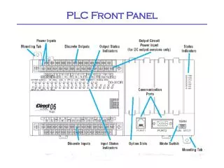
Digital Interface SM-USB-DIG
Stage 2 Interface • Add MCU • Excluded from stage 1 (Rev. A) • MCU controls data converters • MCU communicates through SM-USB-DIG to computer • Adds extra capabilities
Power • Powered by a lab supply for prototyping • Banana plug input jack