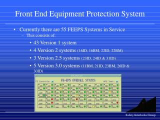
Wireless RF Receiver Front-end System
Wireless RF Receiver Front-end System. Wei-Liang Chen. 2002-10-9. Yuan-Ze University, VLSI Systems Lab. Outline. Communications Infrastructure. Wireless RF Receiver Front-end. Building Blocks. Frequency Synthesizer. Demand in the Feature. Conclusions. References.

Wireless RF Receiver Front-end System
E N D
Presentation Transcript
Wireless RF Receiver Front-end System Wei-Liang Chen 2002-10-9 Yuan-Ze University, VLSI Systems Lab.
Outline • Communications Infrastructure • Wireless RF Receiver Front-end • Building Blocks • Frequency Synthesizer • Demand in the Feature • Conclusions • References
DC(0Hz) Antenna IF Mixer 5.2GHz 2.6GHz I RF Mixer LNA LO 2.6GHz Q LO 2.6GHz IF Mixer Receiver Architecture Two Downconversion ex: 5.8GHz WLAN standard LNA: Low Noise Amplifier LO : Local Oscillator
Antenna LNA Building Blocks * Low Noise Amplifier Noise Source Amplified Signal Small Noisy Signal * The smaller noise contributed form LNA is better
RF IF : Down-conversion RF : Up-conversion IF * Mixer is a frequency converter * LO usually is a frequency synthesizer Building Blocks (cont.) * Mixer & Local Oscillator (LO) Mixer
Frequency Synthesizer • Why need frequency synthesizer? • The crystal oscillator frequency is limited • Synthesis technique provide more flexibility for application • Integration consideration
* Phase Locked Loop (PLL) frequency synthesizer Phase Detector (PD): Serves as an “error amplifier” Loop filter : A low pass filter VCO : Voltage controlled oscillator * The loop is considered “locked” if is constant with time and the output frequency will be Block Diagram of Synthesizer y(t) x(t)
Demand in the Feature • Multi-functions Integrated in one Chip • High Data Transmission Speed • Low Power Consumption
Conclusions Power Supply
References • [1] P. R. Gray, Some Considerations for Multistandard Wireless RF Modems • [2] B. Razavi, Design of Analog CMOS Integrated Circuits. Singapore: McGraw Hill, 2001. • [3] J. Craninckx and M. J. Steyaert, “A 1.8-GHz low-phase-noise CMOS VCO using optimized hollow spiral inductors,” IEEE Journal of solid-state circuits, vol. 32, pp. 736-744, May. 1997. • [4] J. Bhattacharjee et al., ” A 5.8 GHz fully integrated low power low phase noise CMOS LC VCO for WLAN applications,” in Proc. IEEE Microwave Symposium Digest, 2002, pp.585-588.


![[ WIRELESS RECEIVER : SHURE. GLXD1]](https://cdn3.slideserve.com/6379252/slide1-dt.jpg)