Download
1 / 18
180 likes | 467 Vues
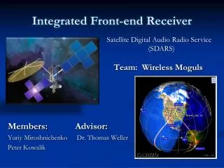
Satellite Digital Audio Radio Service Receiver Front-End (SDARS). Albert Kulicz Greg Landgren Advisor: Dr. Prasad Shastry. SDARS. What is SDARS Overall System Block Diagram Patch Antenna L ow N oise A mplifiers (LNA) Equipment and Parts List Tasks for Next Semester. What is SDARS?.

E N D
Satellite Digital Audio Radio ServiceReceiver Front-End(SDARS) Albert Kulicz Greg Landgren Advisor: Dr. Prasad Shastry
SDARS What is SDARS Overall System Block Diagram Patch Antenna Low Noise Amplifiers (LNA) Equipment and Parts List Tasks for Next Semester
What is SDARS? The Satellite Digital Audio Radio Service is primarily for entertainment broadcasting from orbital satellites and received by modules commonly found on modern automobiles. (ex: XM or Sirius Radio) This project involves designs, simulations, fabrication, and testing of a patch antenna and low-noise amplifier (LNA) to receive SDARS signals by means of SIRIUS receiver. The inclusion of the entire active antenna (passive antenna + impedance matching network + LNA) will be designed to minimize physical size, while producing the best quality of signal.
System Block Diagram Incoming Circularly Polarized Satellite Signal (-105 to -95)dbm
Antenna and LNA physical board design Compared to past SDARS projects, our design will contain the entire active antenna on a single “board” consisting of two substrates as seen below.
Patch Antenna Passive portion of the active antenna Receives incoming signal from satellite Design Goal – Make it smaller than previous SDARS attempts and stay within the specified requirements
Antenna Requirements Receive signals in the frequency band from 2.32 GHz to 2.3325 GHz (BW of 12.5 MHz) Left Hand Circular Polarization (LHCP) Match in impedance to LNA network (~50 Ohms) Probe Feed – Placement will determine polarization and impedance match
Antenna Requirements Cont… Desired: VSWR <2 or S11<-10 dB , fo = 2.326 GHz , 12.5MHz BW
Antenna Impedance Bandwidth .012 %BW = BW/fo = (12.5M Hz/2.326 GHz) * 100% = 0.537%
Antenna Dimension Equations [1] Balanis, Constantine A, “Microstrip Antennas,” in Antenna Theory, 3rd ed. John Wiley and Sons, Inc., 2005, pp. 811-882 (L=W for square patch) Initial length L = c/(2fo* εr^(1/2)) εeff= (εr+1)/2 + (εr-1)/2*[1+12(h/L))^(-1/2) Fringe factor, ΔL=0.412 h (ε eff + 0.3)( W/h + 0.264) / ( (ε eff - 0.258)(W/h + 0.8)) New length L = c/(2fo* εeff^(1/2)) - 2ΔL repeat iterative process 3.692cm x 3.692 cm
LHCP and Probe Feed • SDARS signal from satellite is LHCP so the antenna must also be LHCP to receive the signal LHCP Probe Feed on Patch Antenna • Using CPPATCH program we determined the distance from the center to edge (along diagonal) to be 0.382 cm
Low Noise Amplifers (LNA) The LNA network will take the low-power satellite signal and amplify it to a level where the Sirius receiver can reliably decode the radio channels A cascaded network of LNAs will allow us to achieve both a low total noise factor and a high total gain Two stages of amplification will suffice
LNA Requirements Noise factor shall be <= 1dB NF = F1 + (F2 -1)/G1 + (F3-1)/(G1*G2)+ . . . Total gain shall be -> 40~50 dB Gtotal = G1+ G2 + . . .
Hittite LNAs Second stage Higher Gain First stage NF <.9dB Total Noise Factor = 0.77 Total Gain = 45 dB
Parts and Equipment RO3003 substrate Sirius Radio Receiver LNA substrate - tbd HMC548LP3 LNA HMC667LP2 LNA MCL15542 DC Blocking Capacitor • EM Simulation Software (Sonnet / Momentum) • PCAAD • Agilent ADS • CPPATCH • Network Analyzer • Spectrum Analyzer • Frequency Generator • Power Supplies
Tasks for Next Semester Complete EM simulations with Sonnet and Momentum and optimize antenna design (Feb) Test LNA evaluation boards with NA (Feb) Design Impedance Matching for the LNA network (Feb) Design Bias Circuitry for the LNAs (March) Simulate entire active antenna in Agilent ADS (March) Outsource Fabrication of Substrates (March) Test Fabricated Antenna and LNA Substrates (April) Test complete system active antenna board with Sirius Receiver (April)
QUESTIONS ???