Download
1 / 64
640 likes | 879 Vues
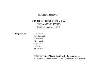
STEREO IMPACT CRITICAL DESIGN REVIEW SWEA (CESR PART) 2002 November 20/22. Prepared by : C. Aoustin J.A. Sauvaud A. Fedorov J.L. Medale J. Rouzaud H.Perrier Th.Moreau

E N D
STEREO IMPACT CRITICAL DESIGN REVIEWSWEA (CESR PART)2002 November 20/22 Prepared by : C. Aoustin J.A. Sauvaud A. Fedorov J.L. Medale J. Rouzaud H.Perrier Th.Moreau CESR – Centre d’Etude Spatiale des Rayonnements 9 Avenue du Colonel Roche – 31028 Toulouse Cedex France CDR - 1
SWEA-CESR PART CDR - 3
MODEL PHILISOPHY • TWO ENGINEERING TEST UNITS – ETU – WILL BE ASSEMBLED • One with a limited number of preamplifiers and without retractable cover • 90° equipped with grids and 7 amplifiers installed for calibration purpose. • delivered to UCB (2002 September 26) for interface test, software testing and UCB test setup checkout • One "complete" • It will be used at CESR to prepare calibrations : under fabrication • TWO FLIGHT MODELS • SPARE PARTS (not assembled) CDR - 4
SWEA REQUIRED CAPABILITIES • Measure wide energy range ~ 1eV to 5000 eV with high spectral and angular resolution • At low energy (<20 eV) have the capability to : • Improve the nominal energy resolution • Reduce geometrical factor • Field of view • 360° in a plane, combined with +/- 65° coverage in elevation out of plane • Space resolution : 22,5 degrees x 10 degrees • Geometrical factor 0,03 cm2 ster keV/keV • Maximum count rate (per sector) : 2.105 counts/sec • Complete 3-D energy-angular spectra in 2 sec • Low power, low weight CDR - 5
SWEA-CESR OVERALL CUTOFF CDR - 6
SWEA-CESR 3D CUT CDR - 7
INTERFACES • Mechanics interfaced with UCB part containing the digital electronics • See next slide • Purging tube going through holes at the center of electronics boards to the MCP (see overall cutoff) • Output connection on Z axis direction • Connector Swagelok A-400-6-1 (1/4 – 1/16) • MCP is located in close space between the mounting board and the outer hemisphere • Venting through small holes in the mounting board • Electrical connection with the interface board (UCB) with a pig-tail connector (Micro-D 51 pin see ICD) CDR - 8
UCB PEDESTAL INTERFACE CDR - 9
Purging Reference axis CDR - 10
SWEA SIZE CDR - 11
MASS ALLOCATION SUB SYSTEM ESTIMATE ALLOCATION Detector support, spheres 297 1 210 g Top hat, pin puller, grids, deflector 303 MCP board 70 Preamplifier board 80 HVPS board 150 Mechanical housing 103 Connector, cabling… 45 _____ Total 1 048 g Not included : • Thermal blanket • Heaters and thermoswitches CDR - 12
POWER ALLOCATION AND STATUS SUBSYSTEM PHASE A CURRENT TEST CONDITIONS (mW) (mW) Preamplifiers dis. 100 100 HVPS MCP 250 211 – 230 Vs = 2500 V R = 50MΩ HVPS analyzer 100 45 min CL = 20pF 102 max HVPS deflectors 60 40 min 140 max Vo voltage 30 50 ___ _______ Total 540 446 min 662 max Allocation 540 mW CDR - 13
SWEA CONTROLLING DOCUMENTS • Stereo impact • Performance specfications Vers H 2002-May-09 • Stereo impact • SWEA UCB to CESR Interface Control Document Vers E 2002-Mar-29 • Stereo impact • Harness specification Vers D 2001-Sept-26 • Grounding Diagram Rev E 2002-Apr-12 • Stereo impact • Performance Assurance Implementation Plan Vers E 2002-Apr-02 • Stereo • Contamination Control Plan Rev B 7381-904C • Stereo • Environnment Definition, Observatory,Component • and Instrument Test Requirements Document Rev E 7381-9003 • EMC • Guidelines for the STEREO Instruments 24-jan-00 CDR - 14
SWEA REVIEW HISTORY • PDR : • 11-12 September 2001 • Presentation by Francis Cotin • DOOR MECHANISM PEER REVIEW • 25 September 2002 in Toulouse CDR - 15
DETAILED DESIGNS DETAILED DESIGNS CDR - 16
SWEA ANALYZER DESCRIPTION • An electrostatic optics is made of : • Top-hat electrostatic analyser with 360° field of view. • Top-hat and external hemisphere are under variable negative potential V0 • Elevation angle electrostatic scanner • 2 toroidal grids : • outer one at spacecraft ground • inner one at Vo potential • Microchannel plate detector – chevron stack of ring shape • 16 sectors anode to provide 22,5° resolution in azimuth • A retractable cover CDR - 17
SCHEMA OF ELECTRON ANALYZER CDR - 18
SWEA FRONT END BLOCK DIAGRAM CDR - 19
SWEA FRONT-END ELECTRONICS DESCRIPTION • 16 charge sensitive preamplifiers (CSP) and discriminators : A111 • One non regulated High Voltage Power Supply (HVPS) that supply 3 High Voltages Amplifiers (HVA) programmed by analog voltage levels • Analyzer : HVA (-25 to + 750 volts) • deflector 1 or 2 : HVA (- 25 to + 1500 volts) • One regulated HVPS for MCP (0 to + 3500 volts) • One programmable power supply (Vo : 0 to – 25 volts) CDR - 20
SWEA ANALYZER DESIGN (1/2) • Top-hat analyser parameters are : • Rout = 40,3mmRin = 37,5 mm ΔR/Rin= 0,075 • Energy to analyzer voltage ratio E/qV k = 7 • Energy resolution E/E 10 % • With 50 logarithmic energy steps between E0 = 1eV and E49 = 5000eV • E/E 0,173 and Vmax = 714 Volts Vmin = 0,14 Volt • By applying a Vo potential to the inner toroidal grid, to the deflectors and to the outer hemisphere of the analyzer we can : • Keep constant the energy resolution even for low energy electrons, accelerated by spacecraft potential • Reduce the geometric factor by a factor of 1 + qVo/Eint-2 • This improvement at low energy will be obtained if high voltages and Vo potential are precise and stable CDR - 21
SWEA ANALYZER DESIGN (2/2) • Top hat analyzer • Manufactured with scalloped internal surface • Internal surfaces of analyzer covered with black conducting coating (copper sulfide) • Deflectors • Manufactured in ULTEM gold plated • MCP • Two complete rings stacked with 30 µm space between them • Mounting on board with all high voltage coupling components • One grid in front at Vo potential and entrance of MCP at + 300 volts • Grids • Made of 4 sectors • One support structure in AU2GN with 8 ribs • Retractable cover : actuated with shape memory alloy pinpullerP5-403-10S CDR - 22
FRONT-END ELECTRONICS DESIGN (1/2) • Charge sensitive preamplifier-discriminator : A – 111 F AMPTEK • Threshold adjustables during calibrations between 5. 104 and 5.105 electrons • Pulse width : 260 to 310 µs • Maximum count rate : 2.5 106 cts/s (periodic) • Test input with capacitor designed on the printed circuit • Test pulses delivered by a counter, driven by a programmable frequency up to 1 MHZ • High Voltage Power Supply for MCP • Range : 0 to + 3500 volts • Command : analog voltage 0 to - 5 volts • on/off by enable command • + 28 V supply routed via the enable plug • Housekeeping :analog voltage 0 to + 5 volts CDR - 23
FRONT-END ELECTRONICS DESIGN (2/2) High Voltage Power Supply for analyzer and deflectors • One non regulated power supply generating all voltages required by the high voltage amplifiers (+1700V, -250V, -5VNR, +5VNR, -32V) • On/off by enable command • Housekeeping : analog voltage 0 to + 5 volts • + 28 V supply routed via the enable plug • 3 High Voltage Amplifiers made with high voltage optocouplers developped at CESR • Command analog voltage 0 to –5 volts • Housekeeping : analog voltage –50mV to +5 volts • Current transfer ratio 0,5 % • 3 kV isolation voltage • Slew rate 1 kV/300 µsec (20 pF Load) CDR - 24
PREAMPLIFIER BOARD CDR - 25
HV COUPLING BOARD/TOP CDR - 26
HV COUPLING BOARD/BOTTOM CDR - 27
HV BOARD CDR - 28
SWEA MECHANICAL DESIGN • SWEA consists of an electrostatic optics, 3 electronics boards, one housing • Packaging design is based on having : • The electrostatic analyzer mounted on the MCP Board • The 3 electronics board mechanically assembled together and with feed through contacts for electrical connections • Grid structure is mounted on the housing and support upward deflector, cover and cover actuator • Connection with the interface board (UCB) with a pig-tail connector (micro-D 51 pin) • Electrical cables routed to the top of the instrument through two ribs of the grid structure (cover + 28V, cover Ret, deflector 1 voltage) • Purging tube is going through holes at the center of electronic boards to the MCP located between mounting board and outer hemisphere of the analyzer • Venting by small holes at the base of the analyzer CDR - 29
THERMAL DESIGN MCP requirement • In normal operation instrument will be in the shadow of the satellite • Temperature will be programmed to a set point with the help of an operational heater controlled by software to have the MCP at around 20°C • Heater is composed by 4 resistors (3.16 kΩ each in serie) close to the MCP • Study has been done to avoid any magnetic disturbance when the heater is operating (see rechauffeur.ps from Thomas Moreau) • One sensor will monitor temperature of the MCP CDR - 30
MANUFACTURE, INTEGRATION AND TEST • Mechanical pieces (electrostatic optics and housing) • Study prepared by CESR • Detail manufacturing drawings, machining of all pieces, surface treatment subcontracted to a company in Toulouse - COMAT – working for space instrumentation • Grids manufactured by CORIMA • Mechanical Integration at COMAT facilities with CESR collaboration • Final integration in CESR clean room class 100 • Electronics boards • Detailed schematics prepared by CESR • Lay-out of printed boards, components soldering subcontracted to a company in Toulouse – MICROTEC – working for space instrumentation • Printed boards manufactured by SYSTRONICS at space level • Integration of MCP on HV coupling board at CESR • Electrical tests, vacuum tests at board level and assembly at CESR CDR - 31
Development STATUS • Engineering TEST Unit 1 • Fabricated, assembled and tested (without Cover actuator opening mechanism) • Delivered to UCB September 26, 2002 • Engineering TEST Unit 2 • Mechanical parts fabricated and under surface treatment • Cover actuator opening mechanism fabricated and tested (peer review in Toulouse 25 September 2002) • Electronics boards under fabrication • Will be kept in Toulouse • Mechanical Drawings completed • Electrical drawings completed CDR - 32
Test done on ETU 1 before delivery to UCB 1/6Configuration CDR - 33
Test done on ETU 1 before delivery to UCB 2/6SWEA in vacuum chamber CDR - 34
Test done on ETU 1 before delivery to UCB 3/6MCP characterisation CDR - 35
Test done on ETU 1 before delivery to UCB 4/6Pulse height distribution CDR - 36
Test done on ETU 1 before delivery to UCB 5/6Elevation Energy Response CDR - 37
Test done on ETU 1 before delivery to UCB 6/6Elevation Response CDR - 38
Remaining work before flight build • More precise validation test in Berkeley on the ETU1 • In Toulouse test done at E>2keV only for validation • to be done at E < 2keV at UCB • Grids transparency measurements • Vibration test at qualification level on ETU2 • Thermal test of the door mechanism : -40°C / +50°C CDR - 39
Parts Status 1/2Quality • List of Parts provided : “PartsTemplate CESR_SWEA.xls” • Most of the parts are JTXV or SCC level C • Upscreening and DPA done on LT1024 (amplifiers) by HIREX • Reports : UPS_0122_01.pdf and DPA_2613_01.pdf • Pin D and life test (1000 h) on A111F by HIREX • On going • Total Dose Radiation test done on HV optocouplers by HIREX • total 50krad(Si) - 360 rad(Si)/hour • Report TID_0159.pdf CDR - 40
Parts Status 2/2Delivery • Most of the parts are already in house • Flight MCP are ordered and will be delivered end of January/begining February • Ceramic chips : ordered and will be delivered 01/03/2003. • High Voltage Resistors : special fabrication started. We have requested non coated resistors due to trouble we got on Rosetta. Should have more precise date soon. • Solid tantalum capacitor : quotation requested from AVX. Will have date soon. Delay due to the fact that they are not fabricated anymore by EUROFARAD. We had to look for new distributor and to have no nickel. • 2N5551 and HC4040 : 01/03/2003 • Pin puller : end of November CDR - 41
Materials Status • List of Parts provided : “CESR_DeclMaterial4.doc” 14/10/2002 • Some changes done following comments from GSFC • Solithane replaced by URALANE 5753 A/B LV ordered from VENTICO through Multiparts • VITON replaced by EP851 for the gaskets • Two samples have been sent to Joanne Uber on request from Robert S. Kiwak (GSFC) for outgasing test • One is pure Stycast 1269 • The other one is Stycast 1269 + 2M G3. This means that it is 1 mass of Stycast 1269 + 2 mass of charge G3. CDR - 42
PerformanceMeeting Requirements • energy range 0 to 5000 eV : hardware in place not tested on all range • At low energy (<20 eV) have the capability to : • Improve the nominal energy resolution • Reduce geometrical factor : in place (Vo tested) has to be checked at UCB • Field of view • 360° in a plane : Ok • +/- 65° coverage in elevation out of plane : Ok • Space resolution : 22,5 degrees x 22,5 degrees : Ok • Geometric factor 0,01 cm2 ster E (eV) • Maximum count rate (per 22,5 degree sector) : 1.106 counts/sec • One complete sequence of measurements in 2 sec • Low power, weight : • ETU1 is 948 g without door mechanism – allocation was 1210g CDR - 43
PERFORMANCE ASSURANCE • Small experienced group : P.A integrated into the engineering tasks • PAP (ref : SWEA-AP-0044-CESR) describes the way that the intent of PAR will be met within the constraints of budget and as makes sense for a small group • Hardware development and fabrication work will be performed using CNES and ESA standard PA/QA procedures • PA organisation • Lead by PM C. Aoustin assisted by CNES • EEE Parts J.L. Medale • MMP J. Rouzaud • Reliability • Instrument designed to permit ease of assembly, test, within contraints of mass and power • All designs are internally reviewed before release and manufacturing agreement • Design checked to satisfy derating levels under worst case condition CDR - 44
SAFETY • No exposed high voltages CDR - 45
Contamination : requirements Microchannel plate cleanliness requirements • Sensitive to dust, humidity and hydrocarbons • Discharge could be created by 100 microns particules • Chemical vapors to be avoided • SWEA will have attachement for permanent purging • To stay under clean dry nitrogen purge as much as possible (5 liters/h) • Some hours inside the plastic container filled with clean dry nitrogen is acceptable • Few-hours interruption in the purge flow is acceptable in clean environment • Red tag cover to be removed and cover opened only in a Class 100 clean room • Red tag cover to stay in place as much as possible during I&T CDR - 46
Cleanliness 1/2 Integration done in a Class 100 clean room in CESR in our subcontractor facilities (COMAT – CNES certified) Before that all mechanical parts are cleaned using isopropylic alcohol and dry by nitrogen flux transport between COMAT and CESR done using sealed polyethylene bags elementary pieces and assembled parts are stored in a vacuum chamber staying in the cleanroom in CESR CDR - 47
Cleanliness 2/2 Electronics boards are cleaned after fabrication and soldering of parts by our subcontractor (MICROTEC - space qualified - Cnes certified) - transportation done using antistatic bags - test performed in clean room in CESR - stored in a vacuum chamber before integration - full unit stored in vacuum chamber before calibration Bakeout of the full unit will be performed at UCB CDR - 48
CONCERNS/PLANNED RESOLUTIONS TECHNICAL RISK IDENTIFICATIONCRITICALITY ITEM CRITICALITY ACTION PDR CDR • Weight Minor Detail design action Ok • Grids manufacturing Major Other manufacturer done identified – contact transparency will be established to be checked • Grid transparency Minor Trade off between done structural rigidity TBC by UCB and transparency • Cover actuator Minor Obtain detail Done informations with (see PEER help of UCB Review) • Deflector shape Minor Detail design action Ok • Thermal Major Detail design action heater for Test on a breadboard MCP CDR - 49
Manufacturing • Mechanics : subcontracted to COMAT (Space qualified / CNES agreement) – Toulouse – ETU1 and ETU2 done • FM should be Ok • Grids : subcontracted to CORIMA – Loriol (Rhone Valley) new but work well • Spheres Surface treatment (Black Copper) : Collini-Fluhmann same than on Cluster – Zurich Switzerland • Surface treatment : APS same than on Cluster - Bordeaux • Electronic boards : subcontracted to MICROTEC (Space qualified / CNES agreement) – Labege 10km from Toulouse - worked with them on several missions (Cluster – Rosetta …..) CDR - 50