
8・5 - Field Inspection Items
8・5 - Field Inspection Items. 8.5.1 Visual inspection and verification test of structure and quantity ( 1 ) Photovoltaic module ( 2 ) Support structure for photovoltaic module ( 3 ) Power conditioner ( 4 ) Display system

8・5 - Field Inspection Items
E N D
Presentation Transcript
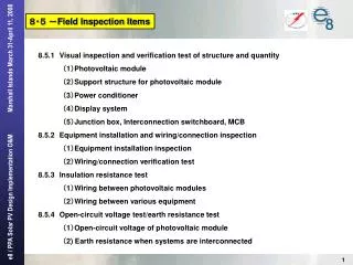
8・5-Field Inspection Items 8.5.1Visual inspection and verification test of structure and quantity (1)Photovoltaic module (2)Support structure for photovoltaic module (3)Power conditioner (4)Display system (5)Junction box, Interconnection switchboard, MCB 8.5.2Equipment installation and wiring/connection inspection (1)Equipment installation inspection (2)Wiring/connection verification test 8.5.3Insulation resistance test (1)Wiring betweenphotovoltaic modules (2)Wiring between various equipment 8.5.4Open-circuit voltage test/earth resistance test (1)Open-circuit voltage of photovoltaic module (2) Earth resistance when systems are interconnected
8.5.1 -Visual inspection and verification test of structure and quantity (1) Photovoltaic module visual inspection and power output test
8.5.1 -Visual inspection and verification test of structure and quantity (2)Visual inspection of Support structure for photovoltaic module array
8.5.1 -Visual inspection and verification test of structure and quantity (3) Power conditioner Visual inspection
8.5.1 -Visual inspection and verification test of structure and quantity (3) Power conditioner Performance test Regarding output inspection/test of relays, check against manufacturers’ shop inspection records on behalf of conducting field inspection/test.
8.5.1 -Visual inspection and verification test of structure and quantity (4)Display system Visual inspection LEDverification test *Input signals from the secondary cable in the transducer inside the interconnection switchboard to verify the indicated values on the LED screen. *Visually check the numerical values indicated by power conditioner panel LCD or data collection system monitor to verify there is no error in the generated electricity of photovoltaic module and inverter output.
8.5.1 -Visual inspection and verification test of structure and quantity (5) Junction box, interconnection switchboard and MCB Visual inspection of junction box-1
8.5.1 -Visual inspection and verification test of structure and quantity (5) Junction box, interconnection switchboard and MCB Visual inspection of interconnection switchboard
8.5.1 -Visual inspection and verification test of structure and quantity (5)Junction box, interconnection switchboard and MCB Visual inspection of MCB
8.5.2 -Equipment installation and wiring/connection inspection (1), (2) Insulation resistance measurement of cable between junction box and inverter panel Insulation resistance measurement of cable between inverter and interconnection witchboard Insulation resistance measurement of cables between interconnection switchboard, MCB and existing transducers [Test procedure] Measure the insulation resistance of (+,-) polarities and (R,S,T) phases of each cable to ensure that there is no insulation failure. Measure the insulation resistance between each cable and the ground (according to the rules for internal cables). [Acceptance criteria] Measured voltage>600V: Acceptable if measurement using 1000V megger shows 0.4MΩ or igher . Measured voltage>300V: Acceptable if measurement using 500V megger shows 0.4MΩ or higher Measured voltage>150V: Acceptable if measurement using 500V megger shows 0.2MΩ or higher. Measured voltage>150V: Acceptable if measurement using 500V megger shows 0.1MΩ or higher.
8.5.2-Equipment installation and wiring/connection inspection >600V >600V >600V >300V >300V >300V
8.5.3 -Equipment installation and wiring/connection inspection (1)、(2) Insulation resistance measurement of cables between photovoltaic modules [Test procedure] Measure the insulation resistance of (+,-) polarities and (R, S, T)phases of each cable for one string of photovoltaic module array to verify that there is no insulation failure. Measure the insulation resistance between each cable and the ground (*The insulation resistance of the cable including the photovoltaic module will be measured). [Acceptance criteria] Open-circuit voltage≧300V: Acceptable if measurement using 1000V megger shows 0.4MΩ or higher .
8.5.4 -Open-circuit voltage test/earth resistance test (1)DC Open-circuit voltage of cables between photovoltaic modules The crystalline photovoltaic power generation system consists of 270 panels of 167 W module. Eighteen modules (167W) in series ×fifteen modules in parallel constitute a photovoltaic power generation system. The open-circuit voltage of one module is about 43.1V(at the highest)with an error of ±10%.Accordingly, the nominal voltage of one module accounts for 43.1V×0.9~1.1=38.79~47.41V. The maximum open-circuit voltage of one circuit consisting of 18 modules will be: 38.8V×18 modules=698.22V (lower limit) 47.4V×18 modules=853.38V (upper limit) [Test procedure] ・Measure the open-circuit voltage of one each string of photovoltaic module array to confirm the polarity of each circuit. ・ Measure the open-circuit voltage of one each string of photovoltaic module array tocheck if the number of modules in series is correct or not. <If the measured voltage is out of the acceptance criteria, the modules in series might be incorrectly connected.>
8.5.4 -Open-circuit voltage test/earth resistance test (1)DC Open-circuit voltage of cables between photovoltaic modules [Test conditions] Tests shall be conducted during daytime hours on a sunny day. (Solar radiation shall be 0.1kW/m2 or higher.) [Acceptance criteria] Measure the open-circuit voltage of one each string of module array to confirm that it meets the following criteria.
8.5.4 -Open-circuit voltage test/earth resistance test (2) Earth resistance measurement [Test procedure] Measure the earth resistance. [Acceptance criteria] Earth resistance of 100 or less is acceptable.