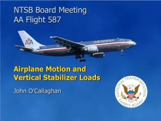
Airplane Motion and Vertical Stabilizer Loads
270 likes | 528 Vues
Airplane Motion and Vertical Stabilizer Loads. John O’Callaghan. Simulation indicates wake encounter. NASA wake study supports encounter. Location of Wake Turbulence Encounters. WIND. FDR accelerations were typical of wake encounters. Crew commented on wake turbulence.

Airplane Motion and Vertical Stabilizer Loads
E N D
Presentation Transcript
NTSB Board Meeting AA Flight 587 Airplane Motion and Vertical Stabilizer Loads John O’Callaghan
Simulation indicates wake encounter • NASA wake study supports encounter Location of Wake Turbulence Encounters WIND • FDR accelerations were typical of wake encounters • Crew commented on wake turbulence • Wake was similar in each encounter
Effect of the Wake Encounters on the Airplane Motion • NASA study indicates nothing unusual about wake. • NTSB simulations determined that the effect of wake on airplane motion was minor. • The airplane was not in or at risk of an upset. NTSB Board Meeting AA Flight 587
First officer responded with column & large wheel inputs • First officer did not use the rudder pedals • Small changes in pitch and roll angles • Airplane motion was unremarkable Control Inputs Following Start of First Wake Encounter Time
Control Inputs Following Start of Second Wake Encounter Time = 09:15:51 • Start of second wake encounter • Airplane in climbing left turn • Controls approximately neutral Time
Large right wheel input • Full right pedal input • Pedal used to help control roll • Pedal not necessary • Wheel alone sufficient to control roll • Full wheel and pedal inputs unnecessary and excessive Control Inputs Following Start of Second Wake Encounter Time = 09:15:52 Time
First full alternating rudder pedal input Control Inputs Following Start of Second Wake Encounter Time = 09:15:53.1 • Full left wheel input (78°) • Full left pedal input Time
Growing oscillation in column inputs Second full alternating rudder pedal input Control Inputs Following Start of Second Wake Encounter Time = 09:15:54.2 • Full right pedal input Time
Wheel moves to large right deflection • Large nose-down column input Control Inputs Following Start of Second Wake Encounter Time = 09:15:55.6 • Full right pedal input maintained Time
Third full alternating rudder pedal input Control Inputs Following Start of Second Wake Encounter Time = 09:15:57 • Full left wheel input • Full left pedal input Time
Fourth full alternating rudder pedal input • Vertical stabilizer separates from airplane Control Inputs Following Start of Second Wake Encounter Time = 09:15:58.4 • Wheel moves right • Full right pedal input Time
Sideslip Angle Buildup Resulting From First Officer’s Control Inputs Sideslip Angle Airflow Airflow • Airplane flew as commanded until vertical stabilizer separation Vertical stab. separation
Calculation of Vertical Stabilizer Loads • Loads dependent on airspeed, sideslip angle, and rudder deflection • Aerodynamic loads determined by wind tunnel testing during airplane development • No wind tunnel data available at the extreme sideslip angle corresponding to vertical stabilizer separation • Other methods required to compute loads at time of separation NTSB Board Meeting AA Flight 587
Computational Fluid Dynamics (CFD) • CFD is the use of computers to mathematically determine the aerodynamic characteristics of airplanes. • CFD is used increasingly in the industry to supplement wind tunnel data and optimize airplane designs. NTSB Board Meeting AA Flight 587
Computational Fluid Dynamics (CFD) • CFD is the use of computers to mathematically determine the aerodynamic characteristics of airplanes. • CFD is used increasingly in the industry to supplement wind tunnel data and optimize airplane designs. • Airbus CFD code has demonstrated capability for solving flow problems such as flight 587 vertical stabilizer loads. • CFD studies directed by NTSB and reviewed by NASA Langley Research Center. NTSB Board Meeting AA Flight 587
CFD Results: Pressure Distribution Over Vertical Stabilizer Pressure Coefficient Chordwise Distance (mm)
Flow Separation CFD Results: Streamlines of Flow at High Sideslip Angle Left Side Right Side
Bending Moment History During Second Wake Encounter Ultimate Load (1.5 x Limit) Limit Load Bending Moment / Limit Load Limit Load Ultimate Load (1.5 x Limit) Time
Bending Moment Base of Vertical Stabilizer
Bending Moment History During Second Wake Encounter Ultimate Load (1.5 x Limit) Limit Load Bending Moment / Limit Load Limit Load Ultimate Load (1.5 x Limit) Time
Bending Moment History During Second Wake Encounter Ultimate Load (1.5 x Limit) Limit Load • Limit load: • Highest load expected in lifetime • Determined by conditions specified in FARs Bending Moment / Limit Load Limit Load Ultimate Load (1.5 x Limit) Time
Bending Moment History During Second Wake Encounter Ultimate Load (1.5 x Limit) Limit Load • Ultimate load: • Equal to limit load times safety factor of 1.5 • Structure must not break up to ultimate load Bending Moment / Limit Load Limit Load Ultimate Load (1.5 x Limit) Time
Range of loads at separation based on wind tunnel & CFD analysis Ultimate Load (1.5 x Limit) Limit Load Wind tunnel analysis Bending Moment / Limit Load Limit Load Ultimate Load (1.5 x Limit) Bending Moment History During Second Wake Encounter 2.5 TAIL BENDS LEFT 2.0 1.5 1.0 0.5 0.0 -0.5 -1.0 -1.5 -2.0 TAIL BENDS RIGHT -2.5 09:15:50 09:15:52 09:15:54 09:15:56 09:15:58 09:16:00 Time
Conclusions Airplane encountered wake turbulence twice • Indicated by FDR, CVR, simulation, and wake analysis First officer’s control inputs following second encounter were unnecessary and excessive • Simulation indicates wake had minor effect on motion • Airplane was never in an upset condition Airplane responded to control inputs as expected until vertical stabilizer separation • Simulation indicates large sideslip angles were the result of control inputs Vertical stabilizer separated at a bending moment load well above ultimate load • Determined by wind tunnel and CFD analysis NTSB Board Meeting AA Flight 587
National Transportation Safety Board American Airlines Flight 587 Belle Harbor, New York November 12, 2001 NTSB Board Meeting October 26, 2004