Download
1 / 32
621 likes | 2.8k Vues
Chapter 6 Fatigue Failure Theories. Fatigue Failure. Occurs when stresses are changing throughout the life of a part. _______________________ starts with a crack that propagates until a catastrophic failure occurs.

E N D
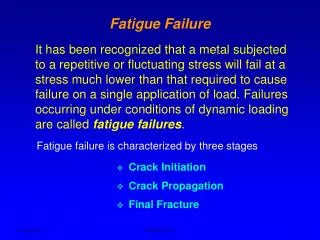
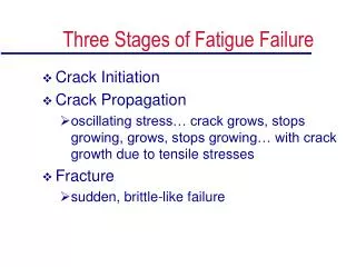
Fatigue Failure • Occurs when stresses are changing throughout the life of a part. • _______________________ starts with a crack that propagates until a catastrophic failure occurs. • This usually begins at a manufacturing defect or stress concentration that is subjected to tensile stresses for part of its load cycle.
Fatigue-Failure Models • Stress-Life - cyclic stresses are kept below fatigue strength or endurance limit. Most widely used. • Strain-Life - complicated not often used. • _________________ - sometimes used, gaining favor especially in the aircraft and aerospace industry.
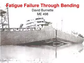
Fully Reversed Failure Criteria • Most data comes from R. R. Moore rotating-beam test. • Highly polished specimen of 0.3 inches in diameter is subjected to pure bending stresses that are alternated by rotating the specimen. • Rotation is at 1725 rpm. • Takes 1/2 day to reach 106 cycles.
Endurance Limit and Fatigue Strength • Endurance Limit of a Material (Se’) - stress below which fatigue failure does not occur regardless of the number of stress cycles. • ____________________Strength of a Material (Sf’) -stress below which fatigue failure does not occur for a specified number of stress cycles.
Estimating Se’ or Sf’ • For ____________:Se’= 0.5Sut for Sut<200 ksi (1400 MPa)Se’= 100 ksi (700 MPa)for Sut>200 ksi (1400 MPa) • For ______________:Se’= 0.4Sut for Sut<60 ksi (400 MPa)Se’= 24 ksi (160 MPa)for Sut>60 ksi (400 MPa)
Estimating Se’ or Sf’ cont’d • For __________________:Sf’@5E8= 0.4Sut for Sut<48 ksi (330 MPa)Sf’@5E8= 19 ksi (130 MPa)for Sut>330 ksi (330 MPa) • For _____________________:Se’= 0.4Sut for Sut<40 ksi (280 MPa)Se’= 14 ksi (100 MPa)for Sut>40 ksi (280 MPa)
Correction Factors to Endurance Limit and Fatigue Strength • Se = CloadCsize CsurfCtempCreliab Se’ • Sf = CloadCsize CsurfCtempCreliab Sf’ • Se -corrected endurance limit for a part • Sf -corrected fatigue strength for a part
Correction Factors to Endurance Limit and Fatigue Strength • Cload - load factor see eq. 6.7a pg 348 • Csize - size factor see eq’s. 6.7a,b,c pg 348-349 • Csurf - surface factor see Fig’s. 6-26, 6.27, and eq. 6.7e pg 349-352
Correction Factors to Endurance Limit and Fatigue Strength • Ctemp - temperature factor see eq. 6.7f pg 352-353 • Creliab - reliability factor see Table 6.4 pg 353
Stress Concentration • Kf = 1+q(Kt + 1) • Kt - geometric stress concentration factor • Kf - ___________________________ • q - notch sensitivity factor
Fluctuating Stresses Modified-Goodman Diagram
Stress Concentration • Apply Kf to the ______________ components of stress. • For __________ materials apply Kt to the mean components of stress.
Stress Concentration - cont’d • If Kf|smaxnom| < Sy then: Kfm = Kf • If Kf|smaxnom| > Sy then: Kfm = (Sy - Kfsanom)/ |smnom| • If Kf|smaxnom - sminnom| < 2Sy then: Kfm = 0
Fluctuating Stresses Multiaxial Stresses in Fatigue
Fluctuating Simple Multiaxial Stresses • Von Mises Method
General Approach to High Cycle Fatigue Design • Generate Modified Goodman Diagram • Calculate alternating and mean components of stress at areas of concern on the part. Include appropriate stress concentration factors. • Convert alternating and mean applied stresses to alternating and mean Von Mises Stresses. • Plot these stresses on the Modified Goodman Diagram and find the factor of safety.
Example • The figure pertains to the shaft of a disk sander that is made from steel having Su=900 MPa, and Sy=750 MPa. The most severe loading occurs when an object is held near the periphery of the disk with sufficient force to develop 12 N-m (which approaches the stall torque of the motor). • Assume a coefficient of friction between the object and the disk is 0.6. • What is the factor of safety with respect to eventual fatigue failure of the shaft?