Chapter 6: Failure Prediction for Static Loading
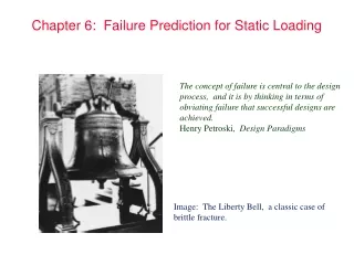
Chapter 6: Failure Prediction for Static Loading. The concept of failure is central to the design process, and it is by thinking in terms of obviating failure that successful designs are achieved. Henry Petroski, Design Paradigms.

Chapter 6: Failure Prediction for Static Loading
E N D
Presentation Transcript
Chapter 6: Failure Prediction for Static Loading The concept of failure is central to the design process, and it is by thinking in terms of obviating failure that successful designs are achieved. Henry Petroski, Design Paradigms Image: The Liberty Bell, a classic case of brittle fracture.
Axial Load on Plate with Hole Figure 6.1 Rectangular plate with hole subjected to axial load. (a) Plate with cross-sectional plane. (b) Half of plate with stress distribution. Text Reference: Figure 6.1, page 221
Stress Concentrations for Plate with Hole Figure 6.2 Stress concentration factor for rectangular plate with central hole. (a) Axial Load. [Adapted from Collins (1981).] Text Reference: Figure 6.2, page 222
Stress Concentrations for Plate with Hole (cont.) Figure 6.2 Stress concentration factor for rectangular plate with central hole. (b) Bending. [Adapted from Collins (1981).] Text Reference: Figure 6.2, page 222
Stress Concentrations for Plate with Fillet Figure 6.3 Stress concentration factor for rectangular plate with fillet. (a) Axial Load. [Adapted from Collins (1981).] Text Reference: Figure 6.3, page 223
Stress Concentrations for Plate with Fillet (cont.) Figure 6.3 Stress concentration factor for rectangular plate with fillet. (b) Bending Load. [Adapted from Collins (1981).] Text Reference: Figure 6.3, page 223
Stress Concentrations for Plate with Groove Figure 6.4 Stress concentration factor for rectangular plate with groove. (a) Axial Load. [Adapted from Collins (1981).] Text Reference: Figure 6.4, page 224
Stress Concentrations for Plate with Groove (cont.) Figure 6.4 Stress concentration factor for rectangular plate with groove. (b) Bending. [Adapted from Collins (1981).] Text Reference: Figure 6.4, page 224
Stress Concentrations for Bar with Fillet Figure 6.5 Stress concentration factor for round bar with fillet. (a) Axial load. [Adapted from Collins (1981).] Text Reference: Figure 6.5, page 225
Stress Concentrations for Bar with Fillet (cont.) Figure 6.5 Stress concentration factor for round bar with fillet. (b) Bending. [Adapted from Collins (1981).] Text Reference: Figure 6.5, page 225
Stress Concentrations for Bar with Fillet (cont.) Figure 6.5 Stress concentration factor for round bar with fillet. (c) Torsion. [Adapted from Collins (1981).] Text Reference: Figure 6.5, page 225
Stress Concentrations for Bar with Groove Figure 6.6 Stress concentration factor for round bar with groove. (a) Axial load. [Adapted from Collins (1981).] Text Reference: Figure 6.6, page 226
Stress Concentrations for Bar with Groove (cont.) Figure 6.6 Stress concentration factor for round bar with groove. (b) Bending. [Adapted from Collins (1981).] Text Reference: Figure 6.6, page 226
Stress Concentrations for Bar with Groove (cont.) Figure 6.6 Stress concentration factor for round bar with groove. (c) Torsion. [Adapted from Collins (1981).] Text Reference: Figure 6.6, page 226
Stress Contours in Bar Figure 6.7 Bar with fillet axially loaded showing stress contours through a flat plate for (a) square corners, (b) rounded corners (c) small groove, and (d) small holes. Text Reference: Figure 6.7, page 229
Modes of Crack Displacement Figure 6.8 Three modes of crack displacement. (a) Mode I, opening; (b) mode II, sliding; (c) mode III, tearing. Text Reference: Figure 6.8, page 231
Yield Stress and Fracture Toughness Data Table 6.1 Yield stress and fracture toughness data for selected engineering materials at room temperature [From ASM International (1989)]. Text Reference: Table 6.1, page 232
Three Dimensional Yield Locus Figure 6.9 Three dimensional yield locus for MSST and DET. [Adapted from Popov (1968).] Text Reference: Figure 6.9, page 236
MSST for Biaxial Stress State Figure 6.10 Graphical representation of maximum-shear-stress theory (MSST) for biaxial stress state (z=0) Text Reference: Figure 6.10, page 237
DET for Biaxial Stress State Figure 6.11 Graphical representation of distortion-energy-theory (DET) for biaxial stress state (z=0) Text Reference: Figure 6.11, page 238
Example 6.6 Figure 6.12 Rear wheel suspension used in Example 6.6. Text Reference: Figure 6.12, page 238
Example 6.7 Figure 6.13 Cantilevered, round bar with torsion applied to free end (used in Example 6.7). (a) Bar with coordinates and load; (b) stresses acting on element; (c) Mohr’s circle representation of stresses. Text Reference: Figure 6.13, page 240
Example 6.8 Figure 6.14 Cantilevered, round bar with torsion and transfer force applied to free end (used in Example 6.8). (a) Bar with coordinates and loads; (b) stresses acting on top of bar and at wall; (c) Mohr’s circle representation of stresses. Text Reference: Figure 6.14, page 241
MNST Theory for Biaxial Stress State Figure 6.15 Graphical representation of maximum-normal-stress theory (MNST) for biaxial stress state (z=0) Text Reference: Figure 6.15, page 243
Internal Friction and Modified Mohr Theory Figure 6.16 Internal friction theory and modified Mohr theory for failure prediction of brittle materials. Text Reference: Figure 6.16, page 244
Comparison of Failure Theories to Experiments Figure 6.17: Comparison of experimental results to failure criterion. (a) Brittle fracture. (b) ductile yielding.
Inserted Total Hip Replacement Figure 6.18 Inserted total hip replacement. Text Reference: Figure 6.18, page 247
Dimensions of Femoral Implants Figure 6.19 Dimensions of femoral implants (in inches). Text Reference: Figure 6.19, page 248
Sections of Implant Analyzed for Static Failure Figure 6.20 Section of femoral stem analyzed for static failure. Text Reference: Figure 6.20, page 248