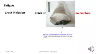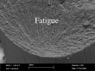
Fatigue failure of material s
Fatigue failure of material s. pre s ented by A s hokkumar t Roll no: 213118006. Introduction to fatigue failure s. Laboratory te s ting v s real life In real life conditions, the component is subjected to several harsh conditions. Cau s e s :

Fatigue failure of material s
E N D
Presentation Transcript
Fatigue failure of materials presented by Ashokkumar t Roll no: 213118006
Introduction to fatigue failures • Laboratory testing vs real life • In real life conditions, the component is subjected to several harsh conditions. Causes: • Fluctuating loads, known as fatigue loads • combined effect of stresses and a corrosive environment • Even abundant materials like water or its vapours, various salts, oils, edible items are known to cause the growth of subcritical cracks to their critical length.
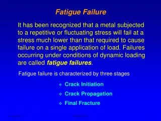
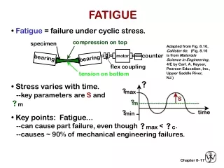
Fatigue and fatigue load • Fatigue: Fatigue is defined as a phenomenon of failure of components under fatigue stress having less than yield strength(ductile material) or less than ultimate strength(brittle material). • Fatigue load: Fatigue load is defined as the load whose magnitude or direction or both magnitude and direction changes w.r.to time and repeatedly applied.
Examples of Fatigue failure Chip off the trunk bit by bit with the saw until the groove becomes so large that the tree can be pulled down easily with a rope. The process is slow but repeated action makes it fall
Axles and shafts shafts are designed to carry torque, but lateral loads, which generate bending moments, cannot be avoided. Consequently, a fiber on the shaft surface which is aligned parallel to the axis is subjected to tensile and compressive stresses in every rotation
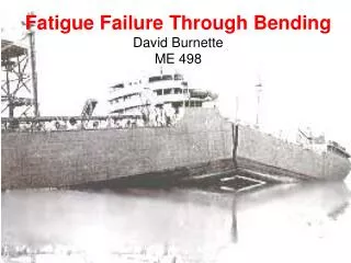
Airplane wings In a newly developed airplane before the flight test , the entire wing is experimentally tested to fluctuating wind loads, simulated in the laboratory, till it fails
Airplane fuselage owing to a fatigue crack growth nucleated near an opening in its fuselage. the fuselage of a plane is subjected to one cycle of pressure per flight because at high altitude the air pressure is increased inside to make it comfortable for the passengers.
stress cycles terminology • There are two kinds of fatigue loads, • Constant amplitude load -loads on locomotive axles • Variable amplitude load -Fluctuating wind load on a wing of an airplane Stress cycle: It is the smallest portion of stress-time plot which is repeated periodically and identically.
S-N Curve • Completely reversed stressed condition is the worst fatigue condition because it is having stress ratio R = -1. • Therefore fatigue test is conducted to determine failure stress under this condition. • Using the Fatigue test machine an empirical relation is determined between applied stress (peak value of the fluctuating load) and number of cycles N required to cause the failure. • The relation is generally known as S-N curve. • At a higher stress, of course, the component has a shorter fatigue life.
Endurance limit: It is defined as the maximum value of completely reversed bending stress that a material can withstand for an infinite no of cycles without a fatigue failure. • For steel, it is found that below the endurance limit the material does not fail. However, distinct endurance limit is not observed for nonferrous metals. • Common practice-design a steel component such that the critical stress does not exceed endurance limit. • For nonferrous metals, conventional design approach has been used to determine allowable stress סa for a reasonable number of cycles, say 10^8 cycles
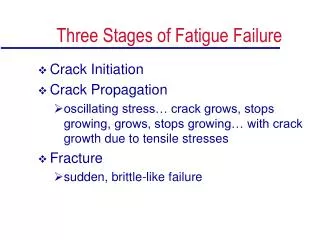
Limitations of s-n curve • An S-N curve adopts a black-box approach and it does not explore the mechanisms of failure. • It does not even distinguish between initiation life and propagation life. • Only overall fatigue life is taken into account. • There is no consideration of the specimen size. • Also, the data on an S-N curve has a large scatter suggesting that the formulation needs to be more rigorous. • A component, designed on the basis of endurance limit, may still fail during its use.