Download
1 / 15
160 likes | 316 Vues
Fatigue Failure Through Bending David Burnette ME 498. Overview. Objectives of experiment Importance and theory Experimental details Result Conclusions and recommendations. Objectives. To become familiar with fatigue testing procedures

E N D
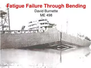
Fatigue Failure Through Bending David Burnette ME 498
Overview • Objectives of experiment • Importance and theory • Experimental details • Result • Conclusions and recommendations
Objectives • To become familiar with fatigue testing procedures • Develop fatigue data for AA 6061-T6 specimens • Extrapolate the endurance limit from the S-N curve (at 5x10^8 cycles) • Compare estimated endurance limit and cycles to failure to known • Evaluate the surface characteristics of fatigue failure
What is Fatigue? Crack Propagation • Examples of Fatigue Factors • Size, loading types • Stress concentration factors • temperature, corrosion
Test Specimens – Cycles to Failure Comparison Aluminum Alloys: Nearly pure (>95%), precipitation hardening, tempering, lack of carbon
3 1 D C B A 4 2 Experimental Setup Bending Stress LOAD Cantilever Arm Motor 6061-T6 specimen
Results • Endurance limit for 6061-T6 alloy at 5x10⁸ • Predicted Cycles to Failure v. Observed • Fracture Surface
Results - Chauvenet N d/σ 5 1.65 6 1.73 7 1.81 8 1.86 9 1.91 10 1.96 12 2.04 14 2.10 16 2.15 18 2.20 20 2.24 1 data point removed with Chauvenet’s: D=σ *(d/σ)
Results - Predicted Cycles Causes of Error eccentricity (set screw), yield strength, diameter, number of points (12)
Results - Surface conditions • Fatigue failure versus dynamic failure • Crack Propagation
Conclusions • Fatigue failure is very different than static or dynamic failures • A small change in diameter can significantly increase the stress • Wide range of deviations (Factor of Safety) • Difference of only 10.5% with eccentricity (human error), diameter uncertainty, alloy uncertainty, etc
Recommendations • Replace set screws with chuck or threaded specimens • Increase size of aluminum specimens (fewer points)