Download
1 / 19
540 likes | 2.95k Vues
Fatigue Failure of Bolted Connections. by: Chris Meisl. Presentation Outline. The Fatigue Process Sequence of Fatigue Failure Behavior of Fatigue Loading S-N Curves Factors Affecting Fatigue Bolted Connections in Tension Location of Failure Preloading and Contact Area Prying Action

E N D
Fatigue Failure of Bolted Connections by: Chris Meisl
Presentation Outline • The Fatigue Process • Sequence of Fatigue Failure • Behavior of Fatigue Loading • S-N Curves • Factors Affecting Fatigue • Bolted Connections in Tension • Location of Failure • Preloading and Contact Area • Prying Action • Bolted Connections in Shear • Preloading • Stress Concentration and Failure Locations • Anchor Bolts • Design Codes Fatigue Failure of Bolted Connections Chris Meisl
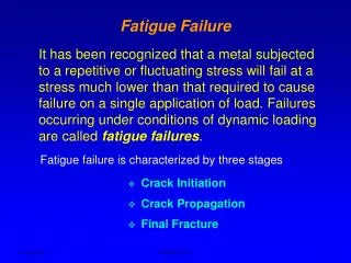
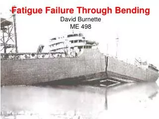
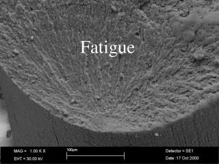
What is Fatigue? • Caused by the repeated application of loads that are not large enough to cause failure in a single application. • Generally caused by repeated cycles of tensile loading. • Failure occurs suddenly. Fracture surface of a paper clip broken by ~6 cycles of repeated bending (80 X) Fatigue Failure of Bolted Connections Chris Meisl
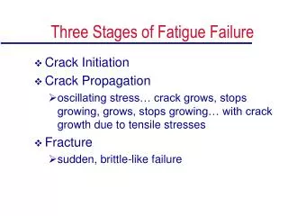
Stages of Fatigue Failure • Failure will only occur if the following essential conditions are present: • Cyclic tensile loads • Stress levels above a threshold value • Flaw in the material • Stages of fatigue failure: • Crack initiation • Crack growth • Crack propagation • Final rupture Fatigue Failure of Bolted Connections Chris Meisl
Behaviour of Fatigue Loading • The fatigue life = the number of repeated cycles of loading (N) that a material will undergo before it fails. • Higher the fatigue stress level, the fewer number of loading cycles required to cause failure. • Major factors that effect fatigue life: • Shape of the connection • Magnitude of stress variations • Mean stress level • Choice of material S-N Curve for varying magnitude of altering stress Fatigue Failure of Bolted Connections Chris Meisl
Bolted Connections in Tension – Failure Locations • Crack is initiated at areas of high stress concentrations. • Potential failure sites: • Head-shank transition • Run-out of thread • Thread at nut • Failure is most likely to occur at the first engagement of the threads of the bolt and nut. Fatigue Failure of Bolted Connections Chris Meisl
Bolted Connections in Tension – Influences • The magnitude of the load on the bolt depends on: • The magnitude of the external tension load. • The bolt-to-joint stiffness ratio (KB/KJ). • Whether or not the external tension load exceeds the critical load required to separate the joint (depends on initial preloading). • Location of the contact area. Fatigue Failure of Bolted Connections Chris Meisl
Bolted Connections in Tension – Non Preloaded Bolts • The external tensile force Ft applied on the connection will be transferred directly to the bolts, Fb. Flange connection with non-preloaded bolts Fatigue Failure of Bolted Connections Chris Meisl
Bolted Connections in Tension – Preloaded Bolts • Preload decreases the load variation in the bolt, until the contact forces Fc are exceeded. Flange connection with preloaded bolts Fatigue Failure of Bolted Connections Chris Meisl
Bolted Connections in Tension – Contact Area • If the flange thickness is to thin bending may occur, leading to contact areas. • Contact area at the centre: • KJ > KB • Low variation of load on bolt until preload is exceeded. • Contact area at edges: • KJ < KB • High variation of load on bolt. • Contact areas located at edges are more susceptible to fatigue. Fatigue Failure of Bolted Connections Chris Meisl
Bolted Connections in Tension – Contact Area Contact force in centre Contact forces located at flange edges Fatigue Failure of Bolted Connections Chris Meisl
Bolted Connections in Shear • Non-Preloading • Load transferred via bearing of bolt shank. • Can not be used in variable load conditions. • Preloaded: • Load transferred by friction between plates. • Use HSFG bolts. • Can be used in variable load conditions. Fatigue Failure of Bolted Connections Chris Meisl
Bolted Connections in Shear • Non-Preloading • Stress concentration at hole. • Fatigue cracks near hole, or shearing of bolt. • Preloaded: • Low stress concentration near hole. • Fatigue cracks at gross section of plate. Fatigue Failure of Bolted Connections Chris Meisl
Anchor Bolts • Behave in the same way as normal bolts. • Bolt diameter and thread size has little effect. • Method of forming thread influences fatigue strength • Rolled threads better than cut due to residual compressive stress. • Double nut increases fatigue resistance. • Must consider prying effects. Fatigue Failure of Bolted Connections Chris Meisl
Code Requirements – CAN/CSA-S16.1-94 • Based on detail categories, number of load cycles, and the corresponding S-N curve. • Considers fatigue failure to occur in the connecting material. • Parameters: g = fatigue life constant [Table 4(a)] n = number of stress range cycles [Table 4(b)] N = number of passages of the moving load Fsrt = constant amplitude threshold range Fatigue Failure of Bolted Connections Chris Meisl
Code Requirements – AISC LRFD 1999 Shear • Based on detail categories, number of load cycles, and the corresponding S-N curve. • Considers fatigue failure to occur in the connecting material and bolt. • Parameters: Fsr = design stress range Cf = constant [Table A-K3.1] N = number of stress range fluctuations Fth = threshold fatigue stress range [Table A-K3.1] At = net tensile area P = pitch db = nominal diameter Tension Category E’ – Cf = 3.9E8 Fth = 48MPa Include prying effects Fatigue Failure of Bolted Connections Chris Meisl
Design Tool – Formatted Spreadsheet Fatigue Failure of Bolted Connections Chris Meisl
Design Tool – Formatted Spreadsheet Fatigue Failure of Bolted Connections Chris Meisl
Conclusions • Fatigue is an important consideration in applications involving repeated loading. • Codes offer little guidance for fatigue of bolted connections. • Avoid fatigue susceptible details. Firth of Forth Rail Bridge Fatigue Failure of Bolted Connections Chris Meisl