Download
1 / 37
370 likes | 524 Vues
Status of COBRA Magnet. W. Ootani ICEPP, University of Tokyo for the MEG collaboration. Construction Status. Detailed design was almost finalized and construction started. Main magnet Detailed mechanical calculations were performed to optimize the mechanical design of the magnet.

E N D
Status of COBRA Magnet W. Ootani ICEPP, University of Tokyo for the MEG collaboration
Construction Status • Detailed design was almost finalized and construction started. • Main magnet • Detailed mechanical calculations were performed to optimize • the mechanical design of the magnet. • Related experimental tests were performed. No problem found. • Winding of the cable is in progress. Central coil was completed. • Construction of the cryostat is starting. • Power supply is being ordered. • Compensation coil • Winding completed and various test were performed. No problem. • Case and support structure are being constructed. • Power supply is being ordered. • Field reconstruction • Accurate calculation based on realistic magnet condition is • under development . • Design work on the mapping machine is starting. • Field reconstruction algorithm is being optimized.
Refrigerator for Main Magnet SHI 4K GM-refrigerator Compressor • Moving part in the refrigerator should be replaced once a year • This maintenance work takes 3-4 weeks. • Quick supporting service is expected from the SHI supporting center • in Germany
Refrigerator for Main Magnet Cold head GM refrigerator Superconducting coil Radiation shield 1m Cryostat
Central coil Winding of Coil Winding of superconducting cable is going on at Toshiba
Construction of Support Shell Support shell for the central and gradient coils completed.
Excitation Test of Central and Gradient Coils • Excitation test of the assembly of the central coil and • two gradient coils with the support shell will be performed • in this summer. • Essential part in the COBRA magnet from the viewpoints • of superconducting and mechanical characteristics. • Design of the experimental setup is almost finished. • This test will be an important milestone in the magnet • construction.
Excitation Test of Central and Gradient Goils • Existing cryostat will be used. • The coils are cooled down to ~4K • using a cold finger from a LHe tank • Possible tests • Quench test • intentional quench caused by a heater • I = 125, 177, 250, 360A (design value) • Superconducting load test • simulate the same load ratio as that • in the final magnet. I = 375A • Axial force test • simulate the same axial force as that • in the final magnet. I = 468A Cryostat 80K shield 20K shield LHe tank Central coil Gradient coil
Current lead Inlet and outlet of cooling water 10 double-pancake layers Compensation Coil • Winding of the hollow conductors • was finished. • All double-pancake windings were • stacked with insulator. • Various tests of the coils were • performed. • Dimension, resistivity, insulation • , water pressure tolerance • , pressure drop, field meas. • , inductance, … • No problem found. • Case for the coil and support • structure are under construction.
Design of Magnet Assembly • Detailed engineering design is almost finalized. • Should be modified for final design of other detector components • and beam transport magnet • Scheme for the survey and alignment is being investigated.
Field Reconstruction • High quality tracking (sp /p ~ 0.3%) requires a precise • knowledge of the magnetic field (magnitude and shape). • Accuracy requirements for the field reconstruction • DB/B ~ 0.1% at each point (DB ~ 10Gauss for 1T) • Essentially two tools for the field reconstruction • Calculation • Field measurement
Field Reconstruction Calculation • Complex of simple air-core solenoids. • g Field is safely calculated by direct application of the Biot-Savart law. • Precise knowledge of the coil geometry is required for an • accurate calculation. • Basic geometrical parameters (radius, length, relative position • , tilt of the coil) can be measured at room temperature prior to • the installation to the cryostat. • g can be extrapolated to the actual operating condition • (at low temperature and with current on) using the well known thermal • expansion rate and magnetic pressure. • Deformation of the coil will be smoothed out by magnetic pressure. • g Roundness ~ 5x10⁻⁴
Field Reconstruction Calculation, cont’d • Relative location of the coil complex to the cryostat can be measured with potentiometers to be equipped in the cryostat. • Alignment between the main magnet and compensation coils is not so important. • The accuracy of the field calculation was 0.2% in the previous experiment (H1) • Accurate calculation will be necessary for an extensive field reconstruction even if the field measurements are performed.
Field Reconstruction Field measurement • Field measurement will be performed after installation at PSI • , if possible, together with the transport solenoid. • 0.1% accuracy achieved in the ALEPH, DELPHI, H1 magnet • Use mapping machine in the previous experiment? • Mapping device with movable Hall probes is • under consideration • Ultrasonic motor or high-torque motor placed far from the magnet • as a motion driver • Non magnetic guide and rail • Three orthogonally oriented Hall sensors
Field Reconstruction Conceptual design of the mapping machine • Positioning resolution < 0.5mm • DB < 10Gauss • Detailed design with cost estimation is under development
Field Reconstruction Field measurement, cont’d • Density of measuring points depends on the algorithm • to interpolate between the measuring points. • Intervals of a few cm in the tracking region (105 measuring points) • How to calibrate an overall scale? • Difficult to use NMR which requires highly-uniform field • at the level of 10-4/cm. • (~10-3/cm at the center of the COBRA magnet) • Field monitoring during the experiment life.
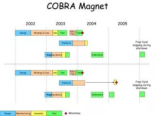
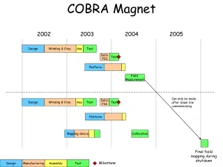
Construction Schedule Schedule of field measurement is not fixed yet.
COBRA spectrometer • Specially designed to form a gradient field • Constant bending radius independent of the emission zenith angle • Quick sweep out of low momentum Michel positrons
Uniform field Gradient field Gradient field Uniform field Concept of COBRA Constant bending radius Quick sweep out
Layout of COBRA magnet • Main SC magnet consists of central, gradient, end coils • Compensation coil consists of a pair of conductive coils • Coil radius is 10% smaller than that in the proposal.
R=0 z Magnetic Field Distribution • Bc = 1.27 T • Bz=1.25m = 0.49 T • Magnitude is larger by 10% • than that in the proposal
Development of SC cable • Superconducting cable with Al stabilizer • Al stabilizer is reinforced • by “micro-alloying technology” • Nickel (5000ppm) is added • into the stabilizer • Overall yield strength ~ 220MPa • while keeping RRR > 280.
SC Cable Performance, cont’d Critical current measured for various temperature and magnetic field Operating condition of COBRA magnet Iop = 360A and Bpeak = 1.7T Cable performance has a safety margin of ~ 30%
y z x Suppression of Stray Field Tolerance to the magnetic field of the PMT • Strong dependence on the field direction relative to the tube axis • Maximum allowed magnitude Bparallel ~ 50Gauss Bperpendicular ~ 150Gauss
Suppression of Stray Field 1400G 3220G parallel 7400G 608G 265G 115G perpendicular 50G Stray field is successfully reduced down to ~50Gauss all over the photon detector by using a pair of compensation coils
sx=sy=0.5mm 1.2mm Point-like target Performance of spectrometer Bending diameter distribution (w/o track fitting) Bending-radius fluctuation is much smaller than that caused by the muon beam spread.
Performance of spectrometer Hit rate of Michel positrons at drift chamber for 108 muons/sec Drift chamber
Performance of spectrometer Distribution of the impact point on the timing counter (R=30cm)
Mechanical Design of Magnet Stress distribution around the central coil Stress level is acceptable for the support shell design
UGEPP UGEPP IX-294 coil Support cylinder (Al) Mechanical Design of Magnet Shearing test to measure the strength of the glueing between the coil and support shell
Mechanical Design of Magnet Shearing test, Result Measured breaking stress ~ 7.8MPa • Almost acceptable • Could be improved by using • another type of insulating tape
Mechanical Design of Magnet Buckling test for support cylinder(1.5mmt) bypassing over the central coil Buckling stress ~ 6.97kg/mm2 gGood! Expected stress ~ 5.4kg/mm2