PNEUMATICS SUBSYSTEM FOR THE BLACKHAWK
110 likes | 232 Vues
This document provides a comprehensive overview of the pneumatic subsystems utilized in the Blackhawk helicopter. It covers various bleed-air sources, including main engines and APU, as well as external sources such as AGPU. Key uses of the pneumatic system include driving engine starters and operating the heating system. The limitations associated with engine starts, anti-ice capabilities, and performance planning considerations are also detailed. In addition, emergency procedures related to engine restarts during flight are outlined, emphasizing the importance of correct usage to ensure operational safety.

PNEUMATICS SUBSYSTEM FOR THE BLACKHAWK
E N D
Presentation Transcript
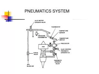
Overview of Pneumatics • Bleed-air sources • 2 main engines • APU • External source (AGPU or “buddy line”) • Uses • Drive the engine starters • Heating system operation • External range fuel system
Overview of Pneumatics (cont’d) • Heating and ERFS • Normally from • Main engines in flight • Main engines or APU • External Source • AGPU • Other Blackhawk • Check valves • Each bleed-air source • Shutoff valve at each main engine
Overview of Pneumatics (cont’d) • APU bleed-air • Start each main engine individually • Both main engines within a reduced range
Limitations • Engine Starter Limits • 60 seconds between cycles • £ 15°C 2 starts, 3 minute rest, 2 starts, 30 minute rest • > 15°C 2 starts, 30 minute rest • Pneumatic Source Inlet • Min. 40 psig & 30 ppm @ 149°C • Max. 50 psig @ 249°C
Limitations (cont’d) • Engine Start Limits • 700 ³ 20,000' may hot start • 701 ³ 18,000' may hot start • Crossbleed Start • Anti-ice light off • Ng ³ 90% • 100% RPMR • Starting >14,000'
Limitations (cont’d) • Engine and Engine Inlet Anti-Ice Limitations • @ £ 10% TRQ, will not have full anti-ice capability • Avoid extreme low power requirement operations • Avoid ground ops <100% RPMR during icing conditions • Cabin heating OFF before starting high rate of descent
Performance Planning Considerations • Engine Anti-ice -16% TRQ +60 lbs/hr • Heater -4% TRQ +20 lbs/hr • Both -20% TRQ +80 lbs/hr
Emergency Procedures CAUTION If TGT rises above 538°C after shutdown, place AIR SOURCE HEAT/START switch as required, turn ENGINE IGNITION switch OFF, and press starter to motor engine for 30 seconds or until TGT decreases below 538°C.
Emergency Procedures (cont’d) ENGINE RESTART DURING FLIGHT After an engine failure in flight, an engine restart may be attempted. If it can be determined that it is reasonably safe to attempt a start, the APU should be used. Use of a crossbleed start could result in a power loss of up to 18% on the operational engine.
Summary • Overview • Limitations (Chap. 5) • Performance Planning factors (Chap. 7) • Emergency Procedures (Chap. 9) STUDY!