Download
1 / 33
350 likes | 645 Vues
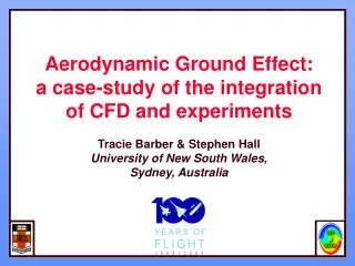
Aerodynamic Ground Effect: a case-study of the integration of CFD and experiments Tracie Barber & Stephen Hall University of New South Wales, Sydney, Australia. Introduction . Ground Effect Issues causing discrepancies in results Boundary Conditions Deformable surface Viscous Effects

E N D
Aerodynamic Ground Effect: a case-study of the integration of CFD and experiments Tracie Barber & Stephen Hall University of New South Wales, Sydney, Australia
Introduction • Ground Effect • Issues causing discrepancies in results • Boundary Conditions • Deformable surface • Viscous Effects • Moving Ground design and analysis • Continuing work
WIG 40 20 0 400 0 -400 -800 -1000 kPa m/s Velocity Pressure
Previous Research • Inviscid (ie panel methods) used extensively • Analytical methods also used (many assumptions, limitations) • Limited viscous CFD results • Inappropriate boundary conditions often used • Experimental results scarce / unreliable
Current Work • Reynolds-Averaged Navier Stokes Equations (CFX & Fluent) • Higher order discretising schemes • RNG or Realizable k-e turbulence model, standard wall functions
Testcases: (2D) • NACA 4412 wing • Angles of attack: • 1.2O, 4O, 6.4O, 10O, 12O • Reynolds Number: • 8,200,000 • Clearances (h/c): • 0.05, 0.10, 0.50, 1.00, free air
Boundary conditions IMAGE SLIP GROUND STATIONARY GROUND MOVING
Results - velocity vectors SLIP IMAGE GROUND MOVING GROUND STATIONARY u=U
PIV Analysis • Particle Image Velocimetry • Pairs of images allow particle movement to be determined • Nd-Yag laser, 532 nm, 100mJ/pulse • Particles of spherical latex (5mm) • Initial investigation considered effect of moving ground
Free Surface Effects • Most WIG craft operate over water • Lifting bodies produce a high pressure on their lower surface • “Does this pressure change the surface shape, and does this affect the aerodynamic characteristics of the body?”
Free Surface Effects • Froude number • Reynolds number: • CFD model (VOF) overcomes this issue
Importance of Viscous Effects • Panel methods (inviscid) frequently used for ground effect • Real flow situations – will viscous effects greatly affect results?
Results: Three-Dimensional • NACA 4412 wing, AR=6 • Angles of attack: • 1.2O, 4O, 6.4O, 10O • Reynolds Number: • 8,200,000 • Clearances (h/c): • 0.05, 0.10, 0.50, 1.00, free air
Effect of Ground on Wake h/c=1.00 h/c=0.05
PIV Results – Flow separation PIV tke CFD tke NACA 4412 wing at 12o, h/c=0.45, trailing edge region PIV tke CFD tke NACA 4412 wing at 12o, h/c=0.05, trailing edge region
Moving Ground • Implementation of moving ground into 3ft x 4ft wind tunnel • Belt speed of 60m/s • Extensive CFD analysis to determine best configuration • Uniform velocity profile • Uniform turbulence profile
Moving Ground - suspended Velocity Contours
Moving Ground – suspended, leadup Velocity Contours
Moving Ground, in line Velocity Contours
Moving Ground, offset, leadup, suction Velocity Contours
Moving Ground - turbulence 100 50 0
Stationary Ground Supersonic Ground Effect (Experimental) Stationary Ground Supersonic Ground Effect (CFD) Moving Ground Supersonic Ground Effect (CFD) Supersonic Ground Effect Shock Wave Validation Cases
Real World Experiment CFD CFD GLUE Integration of CFD & Experiments