Wireless Transmission Line Thermometer
Wireless Transmission Line Thermometer. Group 11 Truman Hwang Eknath Vittal December 1, 2005 ECE 445 Senior Design. 1. Introduction. Wireless Transmission Line Thermometer.

Wireless Transmission Line Thermometer
E N D
Presentation Transcript
Wireless Transmission Line Thermometer • Group 11 • Truman Hwang • Eknath Vittal • December 1, 2005 • ECE 445 Senior Design 1
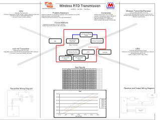
Introduction Wireless Transmission Line Thermometer • The purpose behind this project was to create a infrared thermometer capable of measuring the temperature of a transmission line and send it wirelessly to a computer via RS232 • The ability to measure the temperature of a transmission line allows the user to calculate several important characteristics 2
Wireless Transmission Line Thermometer • Most of the transmission line systems in the power grid today are already constructed. The ability to extract more power and efficiency depends greatly on the increasing the capability of the existing lines. 3
Wireless Transmission Line Thermometer • Determining the temperature during key loading periods such as the summer is an important factor and increasing the capability of a transmission line to carry an increased load. • Temperature is used to calculate sag and tension relationships in the line. Important in determining the load a line can carry as well as the physical nature of the line. 4
Wireless Transmission Line Thermometer Features • Utilizes Extech IR201 Infrared Temperature Sensor • 2 PIC 16F877A Microcontrollers • Linx TXM-315-LC Transmitter and RXM-315-LC-S Receiver • PC Serial Interface via RS232 5
Hardware Wireless Transmission Line Thermometer • Extech IR201 Temperature Sensor • Wide Temperature Range (-58°F to 518°F) • Non-Contact Thermometer 6
Wireless Transmission Line Thermometer • Infrared sensor in the thermometer gathers a small amount of energy (radiation) from the object it is directed at usually around .00001 watts. • This energy is converted into an amplified voltage which is then sent to an ADC • This final signal is processed through an arithmetic unit that coverts the signal into a readable temperature • It is a detector (passively receives radiation) 7
Wireless Transmission Line Thermometer Black Body Radiation • The energy that a sensor focuses on is a result of black body radiation • A blackbody absorbs all the radiation it receives, radiating more thermal radiation for all wavelength intervals. • The rate at which a blackbody radiates energy is given by the Stefan-Boltzmann Law: • w [watts/meter2]= σT[K]4 • σ = Stefan-Boltzmann constant, 5.6697 x 10⁻⁶ watts/m2 – T 8
Wireless Transmission Line Thermometer Hardware • PIC 16F877A Microcontroller • 40 Pin 8-Bit Microcontroller • Powerful and easy to program • Utilized for both sending and receiving data 9
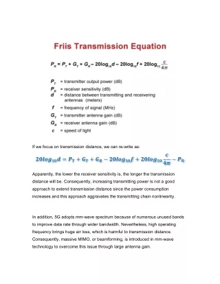
Wireless Transmission Line Thermometer Hardware • The RF Module used in this project transmitted and received at a frequency of 315 MHz • Range of 300 feet with antenna • No external components required except for antenna 10
Wireless Transmission Line Thermometer Hardware • MAX232CPE • Used to interface with PC using RS232 11
Wireless Transmission Line Thermometer Power Supply • To achieve a steady 5 V supply, the power supplies in the lab were used. • To make the device mobile a linear regulator(7805) or converter could be used along with 4 AA batteries for each PIC and transmitter/receiver combination. • The thermometer has an independent supply from 2 AAA batteries. 12
Wireless Transmission Line Thermometer Hardware Interface 13
Wireless Transmission Line Thermometer Temperature Sensor Testing The oscilloscope was connected to the outputs of the temperature sensor 14
Wireless Transmission Line Thermometer These signals were then sent directly into the PIC GP I/O pins. However the current levels out of the sensor did not meet the required values of the PIC. 15
Wireless Transmission Line Thermometer • To resolve this a Digital to Analog converter was used. • This was done to see if the analog signal had enough variance to determine a temperature 16
Wireless Transmission Line Thermometer DAC Circuit A basic DAC circuit was constructed and the out was monitored using the oscilloscope. 17
Wireless Transmission Line Thermometer • The analog signal also did not produce a noticeable variance • A solution to this problem would be to implement a current amplifier to increase the level of the output current to the threshold level required by the PIC (100 mA) • This example circuit shown here has a gain of ten and can raise an input current of 200 uA to 200 mA. 18
Wireless Transmission Line Thermometer PIC Transmitter Software Interface • The Transmitter PIC required an Analog to Digital conversion to take the signal from the temperature sensor and send it to the receiver. Below is a small example of the code required to read the temperature signal from the sensor and continuously send it through the transmitter. • initADC(); • while(FOREVER) • { • readADC(); • transmit(start_code_ID,temp_in/256,end_code); • } 19
Wireless Transmission Line Thermometer PIC Receiver Software Interface • The receiver needed to be continuously receiving the temperature signal. In order to achieve this a while loop was implement with the recieve sub-routine. An example of the pseudo-code can be seen below. • while(TRUE) { • Receive(); • } • if ( kbhit() ) { • j = getc(); • if (j == WAKEUP_ID) { • alert_count = 0; • } • } 20
Wireless Transmission Line Thermometer Successes • Able to achieve wireless transmission • Able to transfer data to PC Areas for Improvement • Redesign temperature sensing circuit, and improve quality and strength of signal
Wireless Transmission Line Thermometer Recommendations • Improve quality of output from the temperature sensor • Develop a sensor on our own that isn’t commercially purchased. This presents a challenge since one does not want to make contact with a transmission line in order to determine the temperature. • If the sensor had worked perform tests on simulated transmission lines such as a power resistor that passes a large amount of current. The heat generated by the resistor would be very similar to those generated by transmission lines. 22
Wireless Transmission Line Thermometer Acknowledgments • Prof. Gary Swenson • Mr. Ishaan Gupta • Mr. Brett Nee 23