ALTERNATING CURRENTS
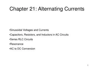
ALTERNATING CURRENTS. Alternating EMF and Current Average or Mean Value of Alternating EMF and Current Root Mean Square Value of Alternating EMF and Current A C Circuit with Resistor A C Circuit with Inductor A C Circuit with Capacitor A C Circuit with Series LCR – Resonance and Q-Factor

ALTERNATING CURRENTS
E N D
Presentation Transcript
ALTERNATING CURRENTS • Alternating EMF and Current • Average or Mean Value of Alternating EMF and Current • Root Mean Square Value of Alternating EMF and Current • A C Circuit with Resistor • A C Circuit with Inductor • A C Circuit with Capacitor • A C Circuit with Series LCR – Resonance and Q-Factor • Graphical Relation between Frequency vs XL, XC • Power in LCR A C Circuit • Watt-less Current • L C Oscillations • Transformer • A.C. Generator Created by C. Mani, Principal, K V No.1, AFS, Jalahalli West, Bangalore
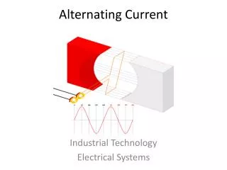
Alternating emf: Alternating emf is that emf which continuously changes in magnitude and periodically reverses its direction. Alternating Current: Alternating current is that current which continuously changes in magnitude and periodically reverses its direction. E0 I0 π/2 π/2 π π 3π/2 3π/2 2π 2π 5π/2 5π/2 3π 3π 7π/2 7π/2 4π 4π t t Symbol of AC Source E = E0 sin ωt E = E0 cos ωt E ,I E ,I I = I0 sin ωt I = I0 cos ωt E0 I0 0 0 θ = ωt θ = ωt T/4 T/2 3T/4 T 5T/4 3T/2 7T/4 2T T/4 T/2 3T/4 T 5T/4 3T/2 7T/4 2T E, I– Instantaneous value ofemfandcurrent E0, I0– Peak or maximum value or amplitude ofemfandcurrent ω – Angular frequency t – Instantaneous time ωt – Phase
T/2 q = ∫ I0 sin ωt dt 0 Average or Mean Value of Alternating Current: Average or Mean value of alternating current over half cycle is that steady current which will send the same amount of charge in a circuit in the time of half cycle as is sent by the given alternating current in the same circuit in the same time. dq = I dt = I0 sin ωt dt q = 2 I0 / ω = 2 I0 T / 2π = I0 T / π Mean Value of AC, Im = Iav = q / (T/2) Im = Iav = 2 I0 / π = 0.637 I0 = 63.7 % I0 Average or Mean Value of Alternating emf: Em = Eav = 2 E0 / π = 0.637 E0 = 63.7 % E0 Note: Average or Mean value of alternating current or emf is zero over a cycle as the + ve and – ve values get cancelled.
T H = ∫ I02R sin2ωt dt 0 Root Mean Square or Virtual or Effective Value of Alternating Current: Root Mean Square (rms) value of alternating current is that steady current which would produce the same heat in a given resistance in a given time as is produced by the given alternating current in the same resistance in the same time. dH = I2R dt = I02Rsin2ωt dt H = I02 RT / 2 (After integration, ω is replaced with 2 π / T) If Iv be the virtual value of AC, then H = Iv2 RT Iv = Irms = Ieff = I0 / √2 = 0.707 I0 = 70.7 % I0 Root Mean Square or Virtual or Effective Valueof Alternating emf: Ev = Erms = Eeff = E0 / √2 = 0.707 E0 = 70.7 % E0 Note: 1. Root Mean Square value of alternating current or emf can be calculated over any period of the cycle since it is based on the heat energy produced. 2. Do not use the above formulae if the time interval under the consideration is less than one period.
0 θ = ωt π/2 π 3π/2 2π 5π/2 3π 7π/2 4π T/4 T/2 3T/4 T 5T/4 3T/2 7T/4 2T t Relative Values Peak, Virtual and Mean Valuesof Alternating emf: E0 Ev Em Em = Eav = 0.637 E0 Ev = Erms = Eeff = 0.707 E0 • Tips: • The given values of alternating emf and current are virtual values unless otherwise specified. • i.e. 230 V AC means Ev = Erms = Eeff = 230 V • AC Ammeter and AC Voltmeter read the rms values of alternating current and voltage respectively. • They are called as ‘hot wire meters’. • 3. The scale of DC meters is linearly graduated where as the scale of AC meters is not evenly graduated because H αI2
I0 y π/2 π 3π/2 2π 5π/2 3π 7π/2 4π t E0 I0 ωt 0 x AC Circuit with a Pure Resistor: R E = E0 sin ωt I = E / R = (E0 / R) sin ωt I = I0 sin ωt E = E0 sin ωt (where I0 = E0 / R and R = E0 / I0) Emf and current are in same phase. E = E0 sin ωt E ,I I = I0 sin ωt E0 0 θ = ωt T/4 T/2 3T/4 T 5T/4 3T/2 7T/4 2T
π/2 π 3π/2 2π 5π/2 3π 7π/2 4π E0 t I0 ωt 0 x π/2 I0 AC Circuit with a Pure Inductor: E = E0 sin ωt L Induced emf in the inductor is - L (dI / dt) In order to maintain the flow of current, the applied emf must be equal and opposite to the induced emf. E = E0 sin ωt I = ∫ (E0 / L) sin ωt dt I = (E0 / ωL) ( - cos ωt ) I = I0 sin (ωt - π / 2) E = L (dI / dt) E0 sin ωt = L (dI / dt) dI = (E0 / L) sin ωt dt (where I0 = E0 / ωL and XL = ωL = E0 / I0) XL is Inductive Reactance. Its SI unit is ohm. Current lags behind emf by π/2 rad. y E = E0 sin ωt E ,I I = I0 sin (ωt - π / 2) E0 0 θ = ωt T/4 T/2 3T/4 T 5T/4 3T/2 7T/4 2T
C π/2 π 3π/2 2π 5π/2 3π 7π/2 4π y E0 t I0 ωt 0 x AC Circuit with a Capacitor: E = E0 sin ωt q = CE = CE0 sin ωt E = E0 sin ωt I = dq / dt = (d / dt) [CE0 sin ωt] I = [E0 / (1 / ωC)] ( cos ωt ) I = I0 sin (ωt + π / 2) (where I0 = E0 / (1 / ωC) and XC = 1 / ωC = E0 / I0) XC is Capacitive Reactance. Its SI unit is ohm. Current leads the emf by π/2 radians. E = E0 sin ωt E ,I I = I0 sin (ωt + π / 2) E0 I0 π/2 0 θ = ωt T/4 T/2 3T/4 T 5T/4 3T/2 7T/4 2T
XL 0 f XC 0 f Variation of XL with Frequency: I0 = E0 / ωL and XL = ωL XL is Inductive Reactance and ω = 2π f XL = 2π f L i.e. XLα f Variation of XC with Frequency: I0 = E0 / (1/ωC) and XC = 1 / ωC XC is Inductive Reactance and ω = 2π f XC = 1 / 2π f C i.e. XCα 1 / f • TIPS: • Inductance (L) can not decrease Direct Current. It can only decrease Alternating Current. • Capacitance (C) allows AC to flow through it but blocks DC.
VR L VL R C VC VL π/2 π/2 VR I π/2 VC E I = √ [R2 + (XL – XC)2] E VL - VC Φ I VR XL – XC ωL – 1/ωC E = √ [VR2 + (VL – VC)2] tan Φ = tan Φ = R R AC Circuit with L, C, R in Series Combination: The applied emf appears as Voltage drops VR, VL and VC across R, L and C respectively. E = E0 sin ωt • In R, current and voltage are in phase. • In L, current lags behind voltage by π/2 • In C, current leads the voltage by π/2 VL - VC 0 I VR E = √ [VR2 + (VL – VC)2] VC Z = √ [R2 + (XL – XC)2] Z = √ [R2 + (ωL – 1/ωC)2] or
XL – XC ωL – 1/ωC tan Φ = tan Φ = R R or Special Cases: Case I: When XL > XC i.e. ωL > 1/ωC, tan Φ = +ve or Φ is +ve The current lags behind the emf by phase angle Φand the LCR circuit is inductance - dominated circuit. Case II: When XL < XC i.e. ωL < 1/ωC, tan Φ = -ve or Φ is -ve The current leads the emf by phase angle Φand the LCR circuit is capacitance - dominated circuit. Case III: When XL = XC i.e. ωL = 1/ωC, tan Φ = 0 or Φ is 0° The current and the emf are in same phase. The impedance does not depend on the frequency of the applied emf. LCR circuit behaves like a purely resistive circuit.
Resonance in AC Circuit with L, C, R: I0 I0max / √2 0 ω When XL = XC i.e. ωL = 1/ωC, tan Φ = 0 or Φ is 0° and Z = √ [R2 + (ωL – 1/ωC)2] becomes Zmin = R and I0max = E / R i.e. The impedance offered by the circuit is minimum and the current is maximum. This condition is called resonant condition of LCR circuit and the frequency is called resonant frequency. At resonant angular frequency ωr, ωr L = 1/ωrC or ωr = 1 / √LC or fr = 1 / (2π√LC) R1 < R2 < R3 I0max Resonant Curve & Q - Factor: Band width = 2 ∆ ω Quality factor (Q – factor) is defined as the ratio of resonant frequency to band width. R1 Q = ωr / 2 ∆ ω It can also be defined as the ratio of potential drop across either the inductance or the capacitance to the potential drop across the resistance. R2 R3 ωr Q = VL / VR or Q = VC / VR ωr - ∆ω ωr + ∆ω or Q = ωr L / R or Q = 1 / ωrCR
Power in AC Circuit with L, C, R: T 0 W = ∫ E0 I0 [sin2ωtcosΦ + sin ωt cosωt cosΦ]dt E = E0 sin ωt I = I0 sin (ωt + Φ) (where Φ is the phase angle between emf and current) Instantaneous Power = E I = E0 I0sin ωt sin (ωt + Φ) = E0 I0 [sin2ωtcosΦ + sin ωt cosωt cosΦ] If the instantaneous power is assumed to be constant for an infinitesimally small time dt, then the work done is dW = E0 I0 [sin2ωt cosΦ + sin ωt cosωt cosΦ] Work done over a complete cycle is W = E0I0 cos Φ x T / 2 Average Power over a cycle is Pav = W / T Pav = (E0I0/ 2) cos Φ (where cos Φ = R / Z = R /√ [R2 + (ωL – 1/ωC)2] is called Power Factor) Pav = (E0/√2) (I0/ √2) cos Φ Pav = Ev Iv cos Φ
Wattless Current or Idle Current: Ev Iv Φ 90° Pav = Ev Iv cos Φ Power in AC Circuit with R: In R, current and emf are in phase. Φ = 0° Pav = Ev Iv cos Φ = Ev Iv cos0°=Ev Iv Iv cos Φ Iv sin Φ Power in AC Circuit with L: In L, current lags behind emf by π/2. Φ = - π/2 Pav = Ev Iv cos (-π/2) = Ev Iv (0)=0 The component Iv cos Φ generates power with Ev. However, the component Iv sin Φ does not contribute to power along Ev and hence power generated is zero.This component of current is called wattless or idle current. P = Ev Iv sin Φcos 90° = 0 Power in AC Circuit with C: In C, current leads emf by π/2. Φ = + π/2 Pav = Ev Iv cos (π/2) = Ev Iv (0)=0 Note: Power (Energy) is not dissipated in Inductor and Capacitor and hence they find a lot of practical applications and in devices using alternating current.
L C Oscillations: L L + + + + + + + + C C L C - - - - - - - - L L L - - - - - - - - - - - C C C + + + + + + + + + + + L L + + + + + + + + L C C C - - - - - - - - At t = 0,UE=Max. & UB=0 At t = T/8,UE = UB At t = 2T/8,UE=0& UB=Max. At t =3T/8,UE = UB At t =5T/8,UE = UB At t = 4T/8,UE=Max.& UB=0 At t = 6T/8,UE=0& UB=Max. At t =7T/8,UE = UB At t =T,UE=Max.& UB=0
0 0 t t 1 f = 2π √LC q0 q0 q q Undamped Oscillations Damped Oscillations If q be the charge on the capacitor at any time t and dI / dt the rate of change of current, then L dI / dt + q / C = 0 The final equation represents Simple Harmonic Electrical Oscillation with ω as angular frequency. So,ω = 1 / √LC or or L (d2q / dt2) + q / C = 0 ord2q / dt2 + q / (LC) = 0 Putting 1 / LC = ω2 d2q / dt2 + ω2 q = 0
Transformer: P S Load Transformer is a device which converts lower alternating voltage at higher current into higher alternating voltage at lower current. Principle: Transformer is based on Mutual Induction. It is the phenomenon of inducing emf in the secondary coil due to change in current in the primary coil and hence the change in magnetic flux in the secondary coil. Theory: EP = - NP dΦ / dt ES = - NS dΦ / dt ES / EP = NS / NP = K (where K is called Transformation Ratio or Turns Ratio) Efficiency (η): η = ESIS / EPIP For an ideal transformer η is 100% For an ideal transformer, Output Power = Input Power ESIS = EPIP ES / EP = IP / IS ES / EP = IP / IS = NS / NP
Load P S P S Load Step - up Transformer: Step - down Transformer: NS > NP i.e. K > 1 ES > EP & IS < IP NS < NP i.e. K < 1 ES < EP & IS > IP Energy Losses in a Transformer: • Copper Loss: Heat is produced due to the resistance of the copper windings of Primary and Secondary coils when current flows through them. • This can be avoided by using thick wires for winding. • Flux Loss: In actual transformer coupling between Primary and Secondary coil is not perfect. So, a certain amount of magnetic flux is wasted. • Linking can be maximised by winding the coils over one another.
Iron Losses: • a) Eddy Currents Losses: • When a changing magnetic flux is linked with the iron core, eddy currents are set up which in turn produce heat and energy is wasted. • Eddy currents are reduced by using laminated core instead of a solid iron block because in laminated core the eddy currents are confined with in the lamination and they do not get added up to produce larger current. In other words their paths are broken instead of continuous ones. b) Hysteresis Loss: When alternating current is passed, the iron core is magnetised and demagnetised repeatedly over the cycles and some energy is being lost in the process. Laminated Core Solid Core This can be minimised by using suitable material with thin hysteresis loop. • Losses due to vibration of core: Some electrical energy is lost in the form of mechanical energy due to vibration of the core and humming noise due to magnetostriction effect.
R S S Q N N S P R1 B1 R2 B2 Load A.C. Generator: Q R P R1 S B1 R2 B2 Load A.C. Generator or A.C. Dynamo or Alternator is a device which converts mechanical energy into alternating current (electrical energy).
Principle: A.C. Generator is based on the principle of Electromagnetic Induction. Construction: • Field Magnet with poles N and S • Armature (Coil) PQRS • Slip Rings (R1 and R2) • Brushes (B1 and B2) • Load Working: Let the armature be rotated in such a way that the arm PQ goes down and RS comes up from the plane of the diagram. Induced emf and hence current is set up in the coil.By Fleming’s Right Hand Rule, the direction of the current is PQRSR2B2B1R1P. After half the rotation of the coil, the arm PQ comes up and RS goes down into the plane of the diagram.By Fleming’s Right Hand Rule, the direction of the current isPR1B1B2R2SRQP. If one way of current is taken +ve, then the reverse current is taken –ve. Therefore the current is said to be alternating and the corresponding wave is sinusoidal.
R Q θ B S Φ = N B A cos ωt Differentiating w.r.t. t, dΦ / dt = - NBAω sin ωt E = - dΦ / dt E = NBAω sin ωt E = E0 sin ωt(where E0 = NBAω) P n E0 0 θ = ωt π/2 π 3π/2 2π 5π/2 3π 7π/2 4π T/4 T/2 3T/4 T 5T/4 3T/2 7T/4 2T t Theory: Φ = N B A cos θ ω At time t, with angular velocity ω, θ = ωt (at t = 0, loop is assumed to be perpendicular to the magnetic field and θ = 0°) End of Alternating Currents