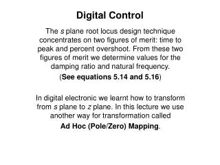
Digital Control Systems: Enhancing Aircraft Technologies
650 likes | 944 Vues
Explore the integration of digital control systems in aircraft technologies for precise and efficient flight mechanisms. Learn about Boeing's advanced flight management computer system and the role of digital control electronics in enhancing aviation safety and performance.

Digital Control Systems: Enhancing Aircraft Technologies
E N D
Presentation Transcript
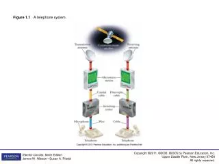
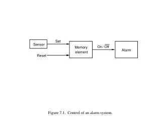
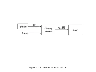
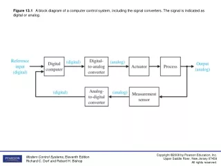
Figure 13.1 A block diagram of a computer control system, including the signal converters. The signal is indicated as digital or analog.
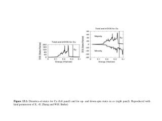
Figure 13.2 The development of INTEL microprocessors measured in millions of transistors. (Source: INTEL.)
Figure 13.3 The flight deck of the Boeing 757 and 767 features digital control electronics, including an engine indicating system and a crew alerting system. All systems controls are within reach of either pilot. The system includes an inertial reference system making use of laser gyroscopes and an electronic attitude director indicator. A flight-management computer system integrates navigation, guidance, and performance data functions. When coupled with the automatic flight control system (automatic pilot), the flight-management system provides accurate engine thrust settings and flight-path guidance during all phases of flight from immediately after takeoff to final approach and landing. The system can predict the speeds and altitudes that will result in the best fuel economy and command the airplane to follow the most fuel-efficient or the “least time” flight paths. (Courtesy of Boeing Airplane Co.)
Figure 13.6 (a) An input signal r(t). (b) The sampled signalThe vertical arrow represents an impulse.
Figure 13.8 The response of a zero-order hold to an impulse input r(kT), which equals unity when k = 0 and equals zero when k ≠ 0, so that r*(t) = r(0)Ϭ(t).
Figure 13.9 The response of a sampler and zero-order hold for a ramp input r(t ) = t.
Figure 13.10 The response of a sampler and zero-order hold to an input r(t ) = e-t for two values of sampling period T.
Figure 13.11 An open-loop, sampled-data system (without feedback).
Figure 13.13 The z-transform transfer function in block diagram form.
Figure 13.14 Feedback control system with unity feedback. G(z) is the z-transform corresponding to G(s), which represents the process and the zero-order hold.
Figure 13.15 (a) Aibo is a sophisticated entertainment robot. Aibo looks like a Chihuahua and wags its tail, does tricks, and goes for walks. Aibo depends on a wide range of sensors, including touch, color CCD camera, range finder, and velocity sensors. A 64-bit RISC microprocessor and 16MB of memory are built in. It has 18 joints powered by 18 motors. Photo courtesy of Sony Electronics Inc. (b) Feedback control system with a digital controller. (c) Block diagrammodel. Note that G(z ) = Z{G0(s)Gp(s)}.
Figure 13.17 The response of a second-order system: (a) continuous (T = 0), not sampled; (b) sampled system, T = 1 s.
Figure 13.19 The maximum overshoot │y│or a second-order sampled system for a unit step input.
Figure 13.20 The loci of integral squared error for a second-order sampled system for constant values of I.
Figure 13.21 The steady-state error of a second-order sampled system for a unit ramp input r(t ) = t, t > 0.
Figure 13.22 The response of a sampled-data second-order system to a unit step input.
Figure 13.23 The continuous system model of a sampled system.
Figure 13.28 A table motion control system: (a) actuator and table; (b) block diagram.
Figure 13.30 (a) Fly-by-wire aircraft control surface system and (b) block diagram. The sampling period is 0.1 second.
Figure 13.31 Elements of the control system design process emphasized in this fly-by-wire aircraft control surfaceexample.
Figure 13.33 Root locus for D(z) = K with the stability and performance regions shown.
Figure 13.36 (a) The tf function. (b) The c2d function. (c) The d2c function.
Figure 13.37 Using the c2d function to convert G(s) = G0(s)Gp(s) to G(z).
Figure 13.38 The step function generates the output y(kT) for a step input.
Figure 13.39 The impulse function generates the output y(kT) for an impulse input.
Figure 13.40 The Isim function generates the output y(kT) for an arbitrary input.
Figure 13.41 The discrete response, y(kT), of a sampled second-order system to a unit step.
Figure 13.42 The continuous response y(t) to a unit step for the system of Figure 13.16.
Figure 13.44 Feedback control system with a digital controller. Note that G(z ) =Z[G0(s)Gp(s)].