Download
1 / 7
70 likes | 171 Vues
Explore various advanced magnetic devices such as tunneling magnetoresistive heads and MRAM elements, with detailed illustrations and explanations. Learn about their components and functions in cutting-edge technology applications.

E N D
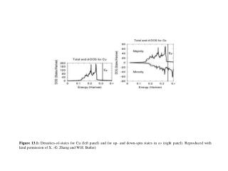
Figure 13.1: Densities-of-states for Cu (left panel) and for up- and down-spin states in co (right panel). Reproduced with kind permission of X..-G. Zhang and W.H. Butler)
Figure 13.2: Schematic figure showing resistivity (solid line) and magnetoresistive ratio (dashed line) as a function of temperature for doped manganite.
Figure 13.3: Cartoon of a four-terminal EMR device consisting of a semiconductor annulus (hatched) with the center cylinder filled with a high-conductivity metal.
Figure 13.5: Cartoon of the magnetic layers in a permanent-magnet biased spin valve read head indicating the magnetization directions of the biasing magnets, of the free layer (FL), reference layer (RL), and pinned layer (PL).
Figure13.6: Cross-section of a tunneling magnetoresistive head stack. The tunneling barrier is indicated by the solid black layer. The current direction is CPP, indicated by the arrow.
Figure 13.7: Cartoon of an MRAM element with bit lines (solid) and word lines (dashed). The current flow in the bit line and through the tunneling stack is indicated by the solid arrows. Current flows only in the bit lines when information is read. To write, current flows in the appropriate word and bit lines which intersect at the bit which is being written.