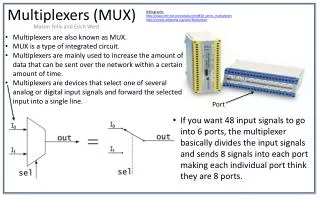
Team MUX
Team MUX. Adam Burton Mark Colombo David Moore Daniel Toler. Introduction. Overview (3) 16 Bit Master-Slave Rising edge registers using transmission gates ALU comprised of 5 functional blocks Adder/Subtractor And Or Shift Multiplier. Team MUX- ALU Block. Output Register Value. `.
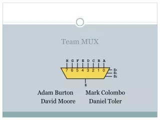

Team MUX
E N D
Presentation Transcript
Team MUX Adam Burton Mark Colombo David Moore Daniel Toler
Introduction • Overview • (3) 16 Bit Master-Slave Rising edge registers using transmission gates • ALU comprised of 5 functional blocks • Adder/Subtractor • And • Or • Shift • Multiplier
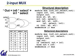
Team MUX- ALU Block Output Register Value ` 16 1 Cout - 1 16 A - 16 16Bit Adder 16Bit OR 16 B - 16 16 Out - 16 16Bit AND 8 -1 MUX 16 16Bit Multiplier 16Bit Shift Control - 3 3 3
Adder/Subtractor Bitslice 1Bit Adder (Mirror) To MUX A X Z B To next bit slice Y Cin Cout SubSignal • In our Adder/Subtractor we had two bit slices with different inverting stages. This was so we could take advantage of the inversion property to cut down on the number of inverters in the carry path.
Shifter Bitslice 1 bit shifter (Passgate Logic) Bundled with other Bitslices Z1 Z2 Z3 Z4 A X B0 B1 Shift Amount • We used passgate logic because the reduced output swing was not an issue, and we could save area.
Functionality Plots Pass c2c1c0=001 A0=0>1 Out0=0>1 CLK A0 A0 Out0 Out0
Functionality Plots AND C2c1c0=110 A0=1>0 B0=0 Out0=1>0 CLK Out0 A0 Out0 A0
Functionality Plots SUB c2c1c0=011 A0=1 B0=1 Out0=0 CLK A0,B0 A0,B0 Out0 Out0
Innovation • Sizing Strategy • What to size • How to size it • Design Trade-Offs • Arbitrary Function – 16 bit multiplier
Sizing • Not on Critical Path Sized to conserve area • On Critical Path Sized for Delay • Attempted Logical Effort Calculations • Result – Tapered Path for reduced delay • Optimized further through simulation • Buffers between registers and ALU
Trade-Offs • Considered Carry Look-ahead Adder • Additional area and power • Small benefit to delay • Supply Voltage • Higher Better Delay, More Power • Lower Worse Delay, Less Power • Decided on Delay due to being squared in metric, used 5V
Innovation in Multiplier • To produce a 16-bit output, need 8-bit multiplier • Team MUX Multiplier is 16 bits • Despite limited output width, offers more flexibility
Multiplier Attributes • The multiplier is a basic array-based multiplier. • Delay through the multiplier • Power consumption of the multiplier
Results • Worst case delay analyzed • 0x7FFF + 0x0001 • Caused all bits to flip • Period: 7ns • Frequency: 143 MHz
Results • Area measurement • Counted up widths • Excluded buffers and multiplier • Width: 4.2115*10^-3 m
Results • Energy calculation • Cycle through all functions with alternating input • Integrated instantaneous power over period of operation • Energy: 2.3426*10^-9 J
Results • Final Metric • D^2*A*E • Metric: 4.846*10-28 s^2*m*J
Conclusion • Meets or exceeds all specifications • Implements all functions • Low metric value • Multiplier is a valuable, common function