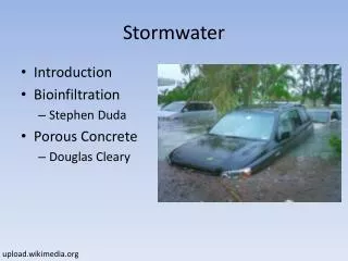
Stormwater C.3 Guidebook
Stormwater C.3 Guidebook. What’s New in the Fifth Edition. Dan Cloak Environmental Consulting May 23, 2011. Topics. Guidebook Objectives and Methods Brief History of Contra Costa’s Approach Review of New Features New Integrated Management Practices New Specifications and Details for IMPs

Stormwater C.3 Guidebook
E N D
Presentation Transcript
Stormwater C.3 Guidebook What’s New in the Fifth Edition Dan Cloak Environmental ConsultingMay 23, 2011
Topics • Guidebook Objectives and Methods • Brief History of Contra Costa’s Approach • Review of New Features • New Integrated Management Practices • New Specifications and Details for IMPs • New Chapter on Construction of IMPs
Objectives and Methods • Objectives • Permit compliance for all projects • Applicants know what they need to submit • Reviewers can determine quickly and with confidence whether a project complies • Projects that work! • Methods • Continuous Improvement • Engage the experience and perspectives of developers, designers, builders, and operators
Guidebook History • First Edition—January 2005 • Based on a manual developed for City of Milpitas • C.3 requirements implemented 2/15/2005 • Second Edition—March 2005 • Basic format and features of the current edition • Emphasis on Drainage Management Areas • 4% sizing factor • Fact sheets from infiltration feasibility study • Third Edition—October 2006 • Met obligation to implement the Hydrograph Modification Management Plan (HMP) approved by the Water Board in June 2006 • More emphasis on Low Impact Development • Policies for Phased Projects and Subdivisions • New IMP sizing factors for HMP compliance • IMP Sizing Calculator • Fourth Edition—October 2008 • March 2007 design charrette to improve IMP designs • Expanded design sheets include many new drawings • LID Design Guide (Chapter 4) • Consolidated and shortened
What’s New – Chapter 1 Page 4
What’s New -- Chapter 1 Page 10 • Alternative Compliance Options • No requirement to demonstrate infeasibility of on-site treatment • 1:1 substitution of impervious area • Must be LID treatment • Should be at least as much pollutant loading • Can combine on-site and off-site treatment • Can also share proportionally in a larger project • Consideration or acceptance of alternative compliance is at the discretion of the municipality
What’s New – Chapter 2 Page 15 • Flow control for projects on sites that are already partially developed *see footnote • Selection of Stormwater Treatment Facilities • First, use LID features that minimize runoff • Assess feasibility of harvesting and (re)use • Two options for (re)use • Storage for two days or less (same volume as a detention basin) • Seasonal storage (60% of mean annual precipitation) Page 16
What’s New – Chapter 3 Page 24 • Assemble Info • Identify Constraints and Opportunities • Prepare and Document Your LID Design • Specify Source Control BMPs • Describe Stormwater Facility Maintenance • Complete Exhibit and Report
What’s New – Chapter 4 • Overall LID Design Approach is retained • Addition of a fifth LID Strategy: • Optimize the site layout • Use pervious surfacesor surfaces that retain runoff • Disperse runoff on to adjacent pervious surfaces • Store runoff and use it later • Direct drainage from impervious surfaces to IMPs Page 35
What’s New – Chapter 4 • Two New IMPs (from 2009 supplement) • Bioretention facilities • Flow-through planters • Cistern + bioretention facilities • Bioretention + vault facilities • Dry wells and other infiltration facilities Page 49
What’s New – Chapter 4 • Incorporated into the IMP Sizng Calculator • New Design Sheets Pages 87, 91
Bioretention FacilityCross-section Not to Scale Overflow structure24" min x 36" min. concrete drop inletor manhole with frame and atrium or beehive grate, ¼ “ openings Curb cut (or curbinlet if neededto ensure runoff capture) 4" min. dia. SDR 35 or equiv. sweep bend and cleanoutmin. 2" above overflow level Walls as needed to establish constant rim elevation around perimeter of facility Adjacent pavement Cobbles or splash block Min. 6" or asneeded to achieve V1 Top of Soil Layer TSL Install all plantings to maintainTSL at or below specifiedelevation 3" max. mulch if specified in landscape plans Male threaded pipe end with cap center-drilled to specified orifice dia. (Omit cap for treatment-only facilities.) Schedule 80 (no perforations)seal penetration with grout Specified soil mix Min. 18“ Top of Gravel Layer TGL 4 " min. dia. SDR 35 or equiv., perforations facing down Min. 12“ or as needed toachieve V2 24" 6" Class 2 perm(Assume 40% porosity for calculation of V2) To storm drain or approved discharge point Bottom of Gravel Layer BGL Large diameter closed perforated pipesor arches may augment storage to achieve V2 Moisture barrier ifneeded to protectpavement or structures Native soil, no compaction. Rip to loosen. • Notes: • No liner, no filter fabric, no landscape cloth. • Maintain BGL. TGL, TSL throughout facility area at elevations to be specified in plan. • Class 2 perm layer may extend below and underneath drop inlet. • Preferred elevation of perforated pipe underdrain is near top of gravel layer. • See Appendix B for soil mix specification, planting and irrigation guidance. • See Chapter 4 for factors and equations used to calculate V1, V2 ,and orifice diameter. Page 76
What’s New – Chapter 5 Page 93 • Based on growing experience with design and construction of bioretention facilities • Construction of Integrated Management Practices • What to show on construction plans • Where to call out elevations • Use cross-sections • Show how runoff moves • Construction checklist
What’s New – Appendix B • Soils, Plantings, and Irrigation for Bioretention Facilities • Originally published as a separate addendum in January 2009 • Soil specification to be implemented throughout the Bay Area • Mix of “concrete sand” (ASTM C33) and compost • Useful guidance on soil and plant installation and plant maintenance • Plant list