Visualization- Determining Depth From Stereo
Visualization- Determining Depth From Stereo. Saurav Basu BITS Pilani 2002. Introduction. Example of Human Vision Perception of Depth from Left and right eye images Difference in relative position of object in left and right eyes. Depth information in the 2 views??.

Visualization- Determining Depth From Stereo
E N D
Presentation Transcript
Visualization-Determining Depth From Stereo Saurav Basu BITS Pilani 2002
Introduction • Example of Human Vision • Perception of Depth from Left and right eye images • Difference in relative position of object in left and right eyes. • Depth information in the 2 views??
Basis for Stereo Imaging LEFT VIEW RIGHT VIEW LEFT EYE RIGHT EYE
The Stereo Problem • The stereo problem is usually broken in to two subproblems • Extraction of Depth information from Stereo Pairs • Use of depth data to visualize the world scene in 3-dimensions by a suitable projection technique.
Stereo Images Depth Estimation Visualization
What are Stereo Images? Images of the same world scene taken from slightly displaced view points are called stereo images. To illustrate how a typical stereo imaging system let us take a look at the camera model for obtaining stereo images
Camera Model Of A Stereo System Image 1 (x1,y1) y x Optical Axis Image 2 (x2,y2) y W (X,Y,Z) x BaseLine distance
Important Points about the Model • The cameras are identical • The coordinate systems of both cameras are perfectly alligned. • Once camera and world co-ordinate systems are alligned the xy plane of the image is alligned with the XY plane of the world co-ordinate system,then Z coordinate of W is same for both camera coordinate systems.
Relating Depth with Image Coordinates X (x1,y1) Z - Z Image 1 Origin Of World Coordinate System B W (X,Y,Z) (x2,y2) Image 2
Important Result • Thus Depth is inversely proportional to (x1-x2) where x1 and x2 are pixel coordinates of the same world point when projected on the stereo image planes. • (x1- x2) is called the DISPARITY • The problem of finding x1 and x2 in the stereo pairs is done by a stereo matching technique.
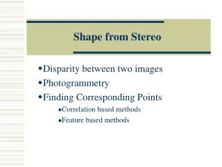
Stereo Matching • The goal of stereo matching algorithms is to find matching locations in the left and right images . • Specifically find the coordinates of the pixel on the left and right images which correspond to the same world point. • It is also called the correspondence problem.
Correlation based approaches • A common approach to finding correspondences is to search for local regions that appear similar • Try to match a window of pixels on the left image with a corresponding sized window on the right image.
Matching Window Matching Pixels Right Image Left Image Diagram to illustrate the Stereo Matching Disparity of this pixel is 1 since x1=0 and x2=1,x2-x1=1 Assumption :Matching Pixels lie on same horizontal Raster Line(Rectified stereo)
The SSD and SAD are commonly used correlation functions SSD:Sum of Squared Deviations SAD:Sum of Absolute Differences
The Multi Window Algorithm • In this algorithm technique 9 different windows are used for calculating disparity of a single pixel. • The window which gives the maximum correlation is used for disparity calculations.
Left Image Right Image Demonstration of the 9 different windows used for the Correlation
Disparity Map • Based on the calculated disparities a disparity map is obtained • The disparity map is a gray scale map where the intensity represents depth. • The lighter shades (greater disparities) represent regions with less depth as opposed to the darker regions which are further away from us.
Visualization • Visualization is the process by which I use the depth estimates from the stereo matching to build projections . • 3-D information can be represented in many ways : -Orthographic projections -Perspective Projections
Perspective Projections • Perspective projections allow a more realistic visualization of a world scene • The visual effect of perspective projections is similar to the human visual system and photographic systems. • Hence perspective projection of the 3-d data was implemented for the stereo pairs.
In Perspective projections the projectors are of finite length and converge at a point called the center of projection. • In perspective projection size of an object is inversely proportional to its distance from ooint of projection A B A’ B’ Projection Plane Projectors Center Of Projection
Specifying a 3-D View • To specify a 3-d view we need to specify a projection plane and a center of Projection: • The Projection plane specified by 1. A point on the plane called the View Reference Point (VRP) 2. The normal to the view plane,i.e. View Plane Normal (VPN)
We define a VRC (View Reference Coordinate system) on the projection plane with u,v,and n being its 3 axes forming a right handed coordinate system • The origin of the VRC system is the VRP • The VPN defines the ‘n’ axis of the VRC system • A View Up Vector (VUP) determines the ‘v’ axis of the VRC system.The projection of the VUP parallel to the view plane is coincident with the ‘v’ axis.
The ‘u’ axis direction is defined such that the ‘u’,’v’ and ‘n’ form a right handed coordinate system. A view Window on the view plane is defined ,projections lying outside the view window are not displayed . The coordinates (Umin,Vmin) and (Umax,Vmax) define this window. The center of projection Projection reference point(PRP).
V Window VUP (Umax,Vmax) CW (Umin,Vmin) VRP U N VPN VIEW PLANE DOP Center of Projection THE 3-D VIEWING REFERENCE COORDINATE SYSTEM
The semi infinite pyramid formed by the PRP and the projectors passing through the corners of the view window form a view volume. • A Canonical view volume is one where the VRC system is alligned with the World Coordinate system.
Back Plane X or Y 1 Front Plane -Z -1 The 6 bounding planes of the canonical view volume have equations: x=z ,x=-z ,y=z, y=-z z=zmin, z=-1 PRP -1 Canonical view volume for Perspective Projections
Perspective projection when VRC alligned with World Coordinate system V P(X,Y,Z) Y U N X P(Xp,Yp,d) PRP CW Z d
Only true when view volume is canonical • For arbitrary view volume -First transform the view volume into canonical form and then apply the above formula to take projections • For transforming a view volume we do the following: 1)Translate VRP to origin 2)Rotate VRC to allign u,v and n axes with the X,Y and Z axes.
3)Translate the PRP to origin 4)Shear to make center line of view volume the the z-axis. 5)Scale such that the view volume becomes the canonical perspective view volume
Z 1. The translation matrix is N VRP U Y 2. The Rotation matrix is V X
4. The Shear Matrix Y CW PRP -Z
5.The scale transformation Y Y=-Z CW PRP -Z Y=-Z
Once all the projected points have been calculated, scale the coordinates to fit the display screen. • A wire frame display of the image is obtained by joining the projections of all points lying on the same row or column. • Map the pixel colors of the image on to the projected points to create a realistic effect.
Limitations • Can work well only for stereo images where minute details are not required. • More suited for depth estimation of landscape through images taken from top. • No accurate metric calculations done.