PRESENTATION ON REACTIVE POWER CONTROL
PRESENTATION ON REACTIVE POWER CONTROL. S.K.SOONEE GM,SRLDC BANGALORE. POWER IS PLEASURE---ASK THOSE WHO ARE SEEKING IT POWER IS PAIN ---ASK THOSE WHO HAVE IT REAL POWER IS PAIN IMAGINARY POWER PLEASURE.

PRESENTATION ON REACTIVE POWER CONTROL
E N D
Presentation Transcript
PRESENTATION ON REACTIVE POWER CONTROL S.K.SOONEE GM,SRLDC BANGALORE
POWER IS PLEASURE---ASK THOSE WHO ARE SEEKING IT • POWER IS PAIN ---ASK THOSE WHO HAVE IT • REAL POWER IS PAIN IMAGINARY POWER PLEASURE
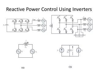
SOURCES OF REACTIVE POWER • SYNCHRONOUS GENERATORS • SYNCHRONOUS CONDENSORS • SHUNT CAPACITORS • STATIC THYRISTOR BASED DEVICES • TRANSMISSION LINES
REACTIVE POWER SINKS • LOADS • INDUCTION MOTORS(PUMPS,FANS ETC) • INDUCTIVE LOADS (CHOKES ETC) • TRANSFORMERS • TRANSMISSION LINES • REACTORS • STATIC THYRISTOR BASED DEVICES • SHYNCHRONOUS MACHINES
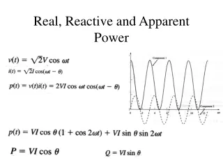
SYNCHRONOUS MACHINEMODES OF OPERATION • UNDER-EXCITED OR LEADING PF • CONSUMES REACTIVE POWER • OVER-EXCITED OR LAGGING PF • PRODUCES REACTIVE POWER vector representation
jIXd δ V θ I SYNCHRONOUS GENERATORSVECTOR DIAGRAM E OVER-EXCITED E jIXd I δ UNDER-EXCITED θ V MORE
CAPABILITY CURVE Q=MVAR, REACTIVE POWER U2=P2+Q2 LEAD MOTORING GENERATING P=MW, ACTIVE POWER LAG MORE
LAG/OVER EXCITED(+) LEAD/UNDER EXCITED(+) LIMITATIONS MORE
TRANSMISSION LINESSIL • SURGE IMPEDANCE LOADING:-The SIL is the loading level where the reactive VARs generated by the line capacitance equal the VARs required by the line inductance. • QUICK FACT: • 100 KM OF 400 KV LINE(MOOSE) CAUSES 55 MVAR OF CHARGING CURRENT MORE
OVERVOLTAGE PROBLEMS • Generator self-excitation • Insulation breakdown • Flashover • Customer equipment damage • Excessive heating of overexcited transformers MORE
UNDERVOLTAGE CAUSES • Heavy line loading • Disturbances • High customer demand • Induction motor heating • Dim lights - more lights • Less heat - more heaters • Voltage collapse MORE
SOME FACTS • A 10 percent voltage drop cuts light output by 30 percent. • A 10 percent voltage drop cuts heat output by 20 percent. The user response, in many such cases, is to turn on more lights MORE
TO CORRECT LOW VOLTAGE • Remove shunt Reactors • Insert shunt capacitors • Energize open lines • Raise LTC set points • Raise voltage regulator set points • Use generator reactive overload capability • Curtail interruptible loads • Shed firm load MORE
TO CORRECT HIGH VOLTAGE • Remove shunt capacitors • Insert shunt reactors • Lower voltage set points • Close open-ended lines or remove from service altogether • Buck with generators • Remove transmission lines from service MORE
POINTS TO REMEMBER • VAR control is the key to voltage control • Use voltage control equipment early • Avoid voltage collapse/High Voltage by smart operating MORE
Permissible Voltage Limits Max permissible Voltage at the far end of lines normally kept energized from one end Voltage Under Normal Condition Nominal (kV) Max Min kV 148 132 145 120 245 220 245 200 420 420 360 400 735/765 800 700 800 MORE
LOAD ANGLE ITS IMPLICATION IN POWER SYSTEM OPERATION
LOAD ANGLE MORE
Frequency and Voltage • “The general synchronous machine equations show that voltage levels are directly proportional to the frequency and for godd voltage control extremes of system frequency are to be avoided” ………Excerpts from Chapter on Reactive Power and Voltage control. System operators Manual L FORMULA
Impact of freq on Voltage E=4.44фfN Where E is the EMF Generated,f is the Frequency, ф the flux PLANNING CRITERIA
Transmission Planning criteria 1. P=P0(F/F0) 2. Q=Q0(V/V0)2 COMPOSITE LOAD MODEL
IEEE MODEL: COMPOSITE LOADS P(V,F)=(A1Vn1Fm1+A2Vn2fm2+A3Vn3Fm3)P0 Q(V,F)=(A4Vn4Fm4+A5Vn5Fm5+A6Vn6Fm6)Q0 CO-EFFICIENTS A1 TO A6 ARE ASSOCIATED WITH LOAD CATEGORIES A1+A2+A3=1 A4+A5+A6=1 LOAD REPRESENTATION
LOAD REPRESENTATION ER GRAPHS
ICT TAPS ON LOAD TAP CHANGER 1.25% OR 5 KV PER TAP±10% RANGE NOMINAL TAP AT 9 TAP NO 1=440/220 400 KV SIDE 220 KV SIDE TAP NO 17=360/220 V V an example
ICT TAP CHANGING EXAMPLE TAP NO 1=440/220 100 MW 50 MVAR 9 400 KV 210 KV TAP NO 17=360/220 V V BASE CONDITION
ICT TAP CHANGING EXAMPLE TAP NO 1=440/220 100 MW 10 MVAR 3 408 KV 208 KV TAP NO 17=360/220 V V TAP IS MOVED FROM 9 TO 3 SAY MVAR FLOW AND RESULTANT VOLTAGES ARE DEPENDANT ON GRID AND STRENGTH OF BUS
TAP CHANGING • REARRANGES MVAR FLOW • TO BE DONE CONSIDERING VOLTAGES ON BOTH SIDES • CO-ORDINATED ACROSS THE SYSTEM • TAP CHANGING SCHEDULES gt taps
400 KV 400 KV 21 KV 21.3 KV ~ ~ INFINITE BUS INFINITE BUS GT TAP CHANGING BASE CASE TAP 9 500 MW 30 MVAR TAP CHANGED TAP 12 500 MW schematic 5 MVAR
REACTIVE LOAD STRATA LOADED LINES LOAD SHEDDING REACTORS REACTORS REMOVAL TRANSFORMERS • BASE LOAD MET BY • CAPACITORS • GENERATORS /LINES BELOW SIL SUPPLYING VAR LOAD LAGGING CAPACITORS LEADING 1.SWITCH OFF CAPACITORS 2.GENERATORS ABSORBING VARS 3.SWITCH OFF LIGHTLY LOADED LINES 4.TAP STAGGERING LIGHTLY LOADED LINES DURATION
VOLTAGE CONTROL WHAT THE IEGC SAYS……..
IEGC SECTION 4.9 • 4.9 Reactive Power Compensation • (a) Reactive Power compensation and/or other facilities, should be provided by SEBs/STUs or distributing agencies as far as possible in the low voltage systems close to the load points thereby avoiding the need for exchange of Reactive Power to/from ISTS and to maintain ISTS voltage within the specified range. MORE
IEGC SECTION 6.9 • 6.9 (J)All generating units shall normally have their automatic voltage regulators (AVRs) in operation, with appropriate settings. In particular, if a generating unit of over fifty (50) MW (10 MW in case of North-Eastern region) size is required to be operated without its AVR in service, the RLDC shall be immediately intimated about the reason and duration, and its permission obtained. Power System Stabilisers (PSS) in AVRs of generating units (wherever provided), shall be properly tuned as per a plan prepared for the purpose by the CTU from time to time. CTU will be allowed to carry out tuning/checking of PSS wherever considered necessary. MORE
IEGC SECTION 6.9 • (q) All regional constituents shall make all possible efforts to ensure that the grid voltage always remains within the following operating range. MORE
IEGC SECTION 6.4 • 6.4 Demand Control • 6.4.1 Introduction: • This section is concerned with the provisions to be made by SLDC's to permit the reduction of demand in the event of insufficient generating capacity, and transfers from external interconnections being not available to meet demand, or in the event of breakdown or operating problems (such as frequency, voltage levels or thermal overloads) on any part of the grid. MORE
IEGC SECTION 6.8 • 6.8 Recovery Procedures • d)The RLDC is authorised during the restoration process following a black out, to operate with reduced security standards for voltage and frequency as necessary in order to achieve the fastest possible recovery of the grid. MORE
IEGC SECTION 7.6 • 7.6 Reactive Power and Voltage Control: 1. The Beneficiaries are expected to provide local VAR compensation/generation such that they do not draw VARs from the EHV grid. However, considering the present limitations, this is not being insisted upon. Instead, VAR drawals by Beneficiaries (except on their lines emanating from ISGS) are to be priced as follows:- - The Beneficiary pays for VAR drawal when voltage at the metering point is below 97%. - The Beneficiary gets paid for VAR return when voltage is below 97%. - The Beneficiary gets paid for VAR drawal when voltage is above 103%. - The Beneficiary pays for VAR return when voltage is above 103%. 2. The charge/payment for VARs, shall be at a nominal paise/kVARh rate as may be approved by CERC from time to time, and will be between the beneficiary and the Pool Account (for VAR interchanges with ISTS), and between two beneficiaries (for VAR interchanges on ties between their systems). 3. Notwithstanding the above, RLDC may direct a beneficiary to curtail its VAR drawal/injection in case the security of grid or safety of any equipment is endangered.
IEGC SECTION 7.6 CONTD…. • 7.6.4In general, the Beneficiaries shall endeavour to minimise the VAR drawal at an interchange point when the voltage at that point is below 95% of rated, and shall not return VARs when the voltage is above 105%. ICT taps at the respective drawals points may be changed to control the VAR interchange as per a beneficiary's request to the RLDC, but only at reasonable intervals. • 5. Switching in/out of all 400 KV bus and line Reactors throughout the grid shall be carried out as per instructions of RLDC. Tap changing on all 400/220 KV ICTs shall also be done as per RLDC's instructions only. • 6. The ISGS shall generate/absorb reactive power as per instructions of RLDC, within capability limits of the respective generating units, that is without sacrificing on the active generation required at that time. No payments shall be made to the generating companies for such VAR generation/absorption.
VA Metering • VA METERING • ACCURACY CLASS • DIFFICULTY IN CALIBRATION AND CHECKING • DIFFICULTY IN MEASURING BAD POWER FACTOR