Chapter Five Reactive power control & Electric Load Management
180 likes | 301 Vues
Understand the importance of reactive power correction and how it optimizes voltage stability, reduces losses, improves equipment capacity, and complies with power factor regulations. Learn about different correction configurations, capacitor rating determination, benefits of compensators, and control methods. Explore electric load management strategies to enhance resource efficiency and reduce peak demand via direct and indirect load control.

Chapter Five Reactive power control & Electric Load Management
E N D
Presentation Transcript
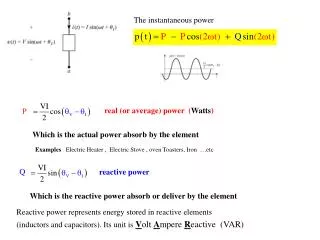
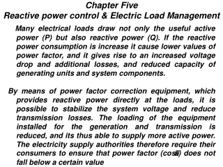
Many electrical loads draw not only the useful active power (P) but also reactive power (Q). If the reactive power consumption is increase it cause lower values of power factor, and it gives rise to an increased voltage drop and additional losses, and reduced capacity of generating units and system components. By means of power factor correction equipment, which provides reactive power directly at the loads, it is possible to stabilize the system voltage and reduce transmission losses. The loading of the equipment installed for the generation and transmission is reduced, and its thus able to supply more active power. The electricity supply authorities therefore require their consumers to ensure that power factor (cos) does not fall below a certain value Chapter Five Reactive power control & Electric Load Management
5.1 Power factor correction configuration: 1- Central Correction: The p.f. correction units are used for central correction directly associated with a main or sub-distribution board. This is suitable when a large number of small loads with different power consumptions switched on for varying periods are connected to the system. 2- Individual Correction: It recommended when a large loads with constant power factor switched on for long periods have to be corrected. The capacitors can be connected directly to the terminals of the individual loads and switched on and off with a common switchgear.
5.1 Power factor correction configuration: 3-Group Correction: In the group correction system one correction unit is associated with each load group. This may consist of motors or fluorescent lamps, connected to the system through a common contactor or switch. In this arrangement, as with individual correction, separate switchgear is often not necessary for switching the capacitors
5.2 Determination of Capacitor Rating: Capacitors draw leading reactive power from the source (i.e. they supply lagging reactive power to the load). The initial value of p.f. ( cos1) is usually known and could be improved to any new required value (cos2). The amount of ( kVAR) to be injected (Qc) is found as;:
5.3 Advantages of reactive power compensator: 1- Voltage drop reduction: Power factor correction, will reduce the reactive current flow in a feeder up to the point of injection, which will reduce the voltage drop up to that point:
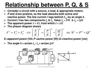
2- Increasing the apparent power capacity (release of system capacity): When the power factor increases, the apparent power (S) for the same active power decreases. The recovered reactive power in percent of the active power demand or the initial kVA demand could be found as:
3- Reduction in line losses: As the p.f. is increased, the line losses are reduced ( because the line current is reduced). Substituting for S2 from eq. 1 in eq. 2:
4- Reduction in transformer losses: The copper losses in a transformer vary with the square of the current and are therefore directly related to the power factor, Then the power losses in transformer after compensation,
5.4 Control Methods: The amount of capacitors connected should be controlled in accordance with load variation as to keep the p.f. and voltage in the design limits. To achieve this, capacitor banks are provided with manual or automatic switching. 1-Time switches, 2-Time switches with voltage over-ride, 3-Voltage sensitive control, 4-kVAR – sensitive control, and 5-cos -sensitive control.
5.5 Electric Load Management: Although the responsibility of electric utilities is to ensure the supply of electric power to its consumers in whatever amount they wish to purchase at whatever time they desire in the most economic way and with the highest standards of reliability. The sharp increase in the costs of new generating capacity, uncertain load growth, increase in fuel prices and other environment and constraints have led to increasing interest in reducing some loads from the peak to the off peak hours by implementing load management program within each utility. Load Management: Is the control of consumer load for the efficient use of resource. The control of load is altering the shape of the annual, seasons, or daily profile.
Benefits of Load Management: 1-Better use of existing generation, transmission, and distribution equipment through control loads. 2-mmediate, selective load shedding in an emergency. 3-Deferment of capital investment for new equipments. 4-Low operating coasts. 5-Increase off-peak energy utilization and hence increase system load factors.
5.6 Load Management Strategies: The main strategies used in load management application are: i-Direct Load Control: Is achieved by utility directly disconnecting, reconnecting the electric devices. ii-Indirect Load Control: Is achieved via an electric tariff rates to encourage the desired load change using two or four seasonal rates per year and two or three rate per day, in which rates are two or four times more expensive during the off-peak hours. This can reduce a time shift of electricity consumption. iii-Energy Storage: Is the use of electricity during off-peak hours to store energy, usually in the form of heat or cool, for use during an on-peak hours.:
The Controllable Loads: Loads suitable for load management program purpose are those which have an inherent storage capability; 1-Electric water heaters, 2-Electric space heating 3-The air conditioners 4-Irrigation pumps & 5- Street lighting
Communication/ control technologies: In order to implement either direct utility control of loads or indirect control via rate structure, some types of control technology is necessary. 1-The Time Switch: In the simplest approach, meter switching or load control is accomplished in situ by a timer actuated switch, which is usually located in the meter enclosure. The advantage of control systems using time switches is their simplicity, which is reflected in the relatively low cost of the hardware. 2-Telephone Systems: The telephone system is a two way communication system between a central control station and controlled locations. It includes the microwave and fiber optics systems.
Communication/ control technologies: 3-Radio Systems: These systems make use of free space propagation and operate mostly on a narrow band FM-UHF of nearly 154MHz. Two way communication systems for load management purposes became possible with extra assignment UHF(928-952)MHz. Advantages of this type are; independent of distribution system, high data rate and could be owned by electric utility. The most disadvantages of this type are; frequency spectrum is limited, the possible interaction of non competent source and the large building can reduce signal propagation. 4-Power Line Carriers (PLC) systems: This system uses the power transmission lines as a medium of communication. They operate in the 5 to 500kHz range. They use low power and generally provide two way communication. The carrier signals can be injected on overhead high voltage lines. At higher frequency the disturbing noise in the power network is rather small, also the signal level can be much lower compared with ripple control. Ripple control is a communication technique for sending information, command signal from one point or location to another point by utilization the electric power transmission and distribution network as a transmission medium.
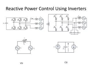
Injection Methods: Signal can be accomplished by using either series or parallel coupling method. The coupling equipment has two functions: 1-Coupling the central signal to the power system with maximum efficiency. 2-Decoupling of the transmitter is prevent power from the system from feeding back into the transmitter. 1- Parallel Injection: The ripple control signal is applied between each phase and neutral. Part of the transmitted power is lost in the transformer and the high voltage side of the power system, represented by impedance Zt and Zs respectively. Since the transformer impedance increases with frequency, it is advantageous to select the highest possible frequency. 2-Series Injection: The transmitter is in series with the load on one side, and the transformer and h.v. system impedance on the other side. The division of voltage will be satisfactory if impedance Zh is less than Z1. Since Zh frequency dependent, it will be lower at low frequency, hence series injection favors the use of low signal frequencies.
Zline = network impedance and equivalent impedance of loads. Zh= h.v. system impedance as seen from the point of injection. Zs =is the h.v. system fault impedance up to the transformer terminals. Zt=the transformer leakage reactance. Zh=Zt+Zs Zp== impedance of parallel coupling unit Zts= series coupling transformer impedance