CHAPTER 37 : INTERFERENCE OF LIGHT WAVES
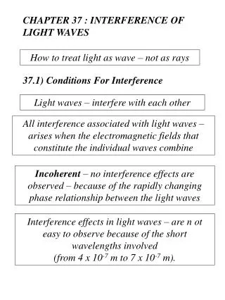
CHAPTER 37 : INTERFERENCE OF LIGHT WAVES. How to treat light as wave – not as rays. 37.1) Conditions For Interference. Light waves – interfere with each other. All interference associated with light waves – arises when the electromagnetic fields that constitute the individual waves combine.

CHAPTER 37 : INTERFERENCE OF LIGHT WAVES
E N D
Presentation Transcript
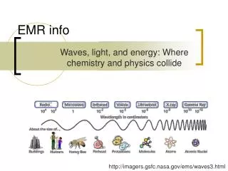
CHAPTER 37 : INTERFERENCE OF LIGHT WAVES How to treat light as wave – not as rays 37.1) Conditions For Interference Light waves – interfere with each other All interference associated with light waves – arises when the electromagnetic fields that constitute the individual waves combine Incoherent – no interference effects are observed – because of the rapidly changing phase relationship between the light waves Interference effects in light waves – are n ot easy to observe because of the short wavelengths involved (from 4 x 10⁻⁷ m to 7 x 10⁻⁷ m).
Conditions or sustained interference in light waves to be observed : The source : coherent – must maintain a constant phase with respect to each other The source : monochromatic – of a single wavelength The characteristics of coherent sources Two sources (producing two traveling waves) are needed to create interference To produce a stable interference pattern –the individual waves must maintain a constant phase relationship with one another
Method for producing two coherent light sources Use one monochromatic source to illuminate a barrier containing two small openings (slits) Light emerging from the two slits is coherent –because a single source produces the original light beam The two slits serve only to separate the original beam into two parts Eg. – the sound signal from the side-by-side loudspeakers Any random change in the light emitted by the source occurs in both beams at the same time – interference effects can be observed when the light from the two slits arrives at a viewing screen
37.2) Young’s Double-Slit Experiment Demonstrated interference in light waves from two sources Figure (37.1a) – A schematic diagram of the apparatus that Young used Light is incident on a first barrier in which there is a slit So The waves emerging from this slit arrive at a second barrier that contains two parallel slits S1 and S2 These two slits serve as a pair of coherent light sources – because waves emerging from them originate from the same wave front and maintain a constant phase relationship The light from S1 and S2 – produces on a viewing screen a visible pattern of bright and dark parallel bands = fringes (Figure (37.1b))
When the light from S1 and that from S2 both arrive at a point on the screen such that constructive interference occurs at that location – a bright fringe appears When the light from the two slits combines destructively at any location on the screen – a dark fringe Figure (37.3) The ways in which two waves can combine at the screen Figure (37.3a) Figure (37.3b) Figure (37.3c) The two waves – which leave the two slits in phase – strike the screen at the central point P The two waves start in phase – but the upper wave has to travel one wavelength farther than the lower wave to reach point Q At point R – midway between point P and Q – the upper wave has fallen half a wavelength behind the lower wave Because both waves travel the same distance – they arrive at P in phase Because the upper wave falls behind the lower one by one wavelength – arrive in phase at Q A trough of the lower wave overlaps a crest of the upper wave Constructive interference – bright fringe Destructive interference – dark fringe A second bright fringe
Figure (37.4) Describe Young’s experiment quantitatively The viewing screen is located a perpendicular distance L from the double-slitted barrier S1 and S2 – separated by a distance d The source is monochromatic To reach any arbitrary point P – a wave from the lower slit travels farther than a wave from the upper slit by a distance d sin = path difference If r1 and r2 are parallel (because L is much greater than d) – then : (37.1) Path difference The value of - determines whether the two waves are in phase when they arrive at point P If = zero or some integer multiple of the wavelength – the two waves are in phase at point P and constructive interference
The condition for bright fringes, or constructive interference, at point P is : (37.2) Order number The central bright fringe at = 0 (m = 0) is called the zeroth-order maximum The first maximum on either side – where m = 1, is called the first-order maximum, and so forth When is an odd multiple of /2 – the two waves arriving at point P are 180o out of phase – destructive interference The condition for dark fringes, or destructive interference, at point P is : (37.3)
Obtain the positions of the bright and dark fringes measured vertically from O to P Assume that L >> d and d >> L = the order of 1 m, d = a fraction of a millimeter, and = a fraction of a micrometer for visible light is small – use the approximation sin tan From triangle OPQ (Figure (37.4)) : (37.4) Solving Eq. (37.2) for sin and substituting the result into Equation (37.4) – the positions of the bright fringes measured from O : (37.5) Using Eq. (37.3) and (37.4) – the dark fringes are located at : (37.6) Young’s doble-slit experiment provides a method for measuring the wavelength of light
37.3) Intensity Distribution of the Double-Slit Interference Pattern The intensity of the light at other points between the positions of maximum constructive and destructive interference Calculate the distribution of light intensity associated with the double-slit interference pattern Suppose that the two slits represent coherent sources of sinusoidal waves – the two waves from the slits have the same angular frequency and a constant phase difference The total magnitude of the electric field at point P on the screen (Figure (37.5)) = the vector superposition of the two waves Assuming that the two waves have the same amplitude Eo – the magnitude of the electric field at point P due to each wave separately : and (37.7)
The waves are in phase at the slits – their phase difference at point P depends on the path difference = r2 – r1 = d sin Because a path difference of (constructive interference) corresponds to a phase difference of 2 rad, the ratio : Phase difference (37.8) Tells how the pahse difference depends on the angle (Figure (37.4)) Using the superposition principle and Eq. (37.7) – the magnitude of the resultant electric field at point P : (37.9) The trigonometric identity :
Taking A = t + and B = t : Eq. (37.9) becomes : (37.10) The electric field at point P has the same frequency as the light at the slits, but the amplitude of the field is multiplied by the factor 2 cos (/2) The light intensity at point P The intensity of a wave is proportional to the square of the resultant electric field magnitude at that point From Eq. (37.10) – the light intensity at point P : The average light intensity at point P : (37.11) The time-average value over one cycle Imax = the maximum intensity on the screen
Substituting the value for (Eq. (37.8)) into Eq. (37.11) : (37.12) Because sin y/L for small valus of in Figure (37.4) – Equation (37.12) becomes : (37.13) Constructive interference (light intensity maxima) – occurs when the quantity dy/L is an integral multiple of , corresponding to y = (L/d)m (Eq. (37.5)) Figure (37.6) – A plot of light intensity versus d sin Valid only if the slit-to-screen distance L is much greater than the slit separation, and only for small values of (the interference pattern consists of equally spaced fringes of equal intensity) The resultant light intensity at a point is proportional to the square of the resultant electric field at that point = (E1 + E2)2
37.6) Interference in Thin Films Figure (37.16) A film of uniform thickness t and index of refraction n Assume that the light rays traveling in air are nearly normal to the two surfaces of the film To determine whether the reflected rays interfere constructively or destructively : A wave traveling from a medium of index of refraction n1 toward a medium of index of refraction n2 – undergoes a 180o phase change upon reflection when n2 > n1 –undergoes no phase change if n2 < n1 The wavelength fo light n in a medium whose refraction index is n is : where = the wavelength of the light in free space (37.14)
Apply these rules to the film of Figure (37.16) – where nfilm > nair Reflected ray 1 (reflected from the upper surface (A)) – undergoes a phase change of 180o with respect to the incident wave Reflected ray 2 (reflected from the lower film surface (B)) – undergoes no phase change because it is reflected from a medium (air) that has lower index of refraction Ray 1 is 180o out of phase with ray 2 – equivalent to a path difference of n/2 Ray 2 travels an extra distance 2t before the waves recombine in the air above surface A If 2t = n/2, then ray 1 and 2 recombine in phase – constructive interference The condition for constructive interference in such situations is : m = 0, 1, 2, … (37.15)
The condition takes into account two factors : The difference in path length for the two rays (the term mn) The 180o phase change upon reflection (the term n/2) Because n = /n m = 0, 1, 2, … (37.16) Conditions for constructive interference in thin films If the extra distance 2t traveled by ray 2 corresponds to a multiple of n – the two waves combine out of phase – destructive interference m = 0, 1, 2, … (37.17) Conditions for destructive interference in thin films
Notes : • The foregoing conditions for constructive and destructive interference are valid when the medium above the top surface of the film is the same as the medium below the bottom surface. • The medium surrounding the film may have a refractive index less than or greater than that of the film. • The rays reflected from the two surfaces are out of phase by 180o. • If the film is placed between two different media, one with n < nfilm and the other with n>nfilm – the conditions for constructive and destructive interference are reversed. • Either there is a phase change of 180o for both ray 1 reflecting from surface A and ray 2 reflecting from surface B, or there is no phase change for either ray – the net change in relative phase due to the reflections is zero.