Download
1 / 1
10 likes | 122 Vues
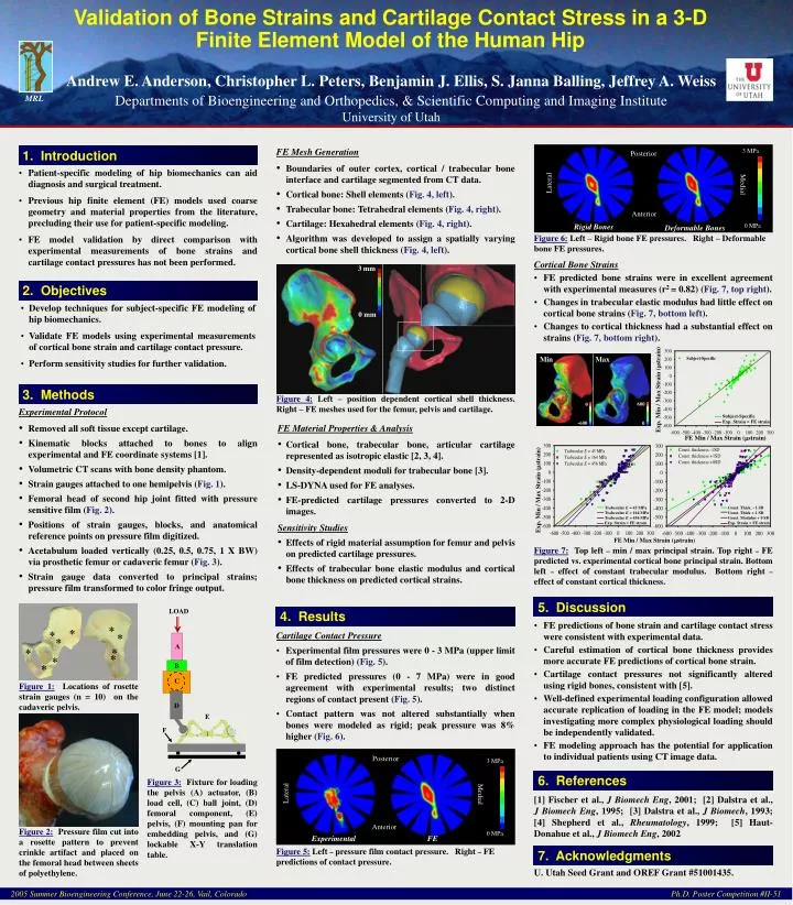
Validation of Bone Strains and Cartilage Contact Stress in a 3-D Finite Element Model of the Human Hip. 3 mm. 0 mm. Andrew E. Anderson, Christopher L. Peters, Benjamin J. Ellis, S. Janna Balling, Jeffrey A. Weiss

E N D
Validation of Bone Strains and Cartilage Contact Stress in a 3-D Finite Element Model of the Human Hip 3 mm 0 mm Andrew E. Anderson, Christopher L. Peters, Benjamin J. Ellis, S. Janna Balling, Jeffrey A. Weiss Departments of Bioengineering and Orthopedics, & Scientific Computing and Imaging InstituteUniversity of Utah MRL 3 MPa Posterior Lateral Medial Anterior 0 MPa Rigid Bones Deformable Bones Figure 6:Left – Rigid bone FE pressures. Right – Deformable bone FE pressures. Min Max Exp. Min / Max Strain (strain) Figure 4:Left – position dependent cortical shell thickness.Right – FE meshes used for the femur, pelvis and cartilage. 600 0 Subject-Specific Exp. Strain = FE strain -600 0 FE Min / Max Strain (strain) Trabecular E = 45 MPa Trabecular E = 164 MPa Trabecular E = 456 MPa Exp. Strain = FE strain Exp. Min / Max Strain (strain) Const. Thick. - 1 SD Const. Thick + 1 SD Const. Modulus + 0 SD Exp. Strain = FE strain FE Min / Max Strain (strain) Figure 7:Top left – min / max principal strain. Top right – FE predicted vs. experimental cortical bone principal strain. Bottom left – effect of constant trabecular modulus. Bottom right – effect of constant cortical thickness. LOAD * * * * * * * * * A * Figure 1:Locations of rosette strain gauges (n = 10) on the cadaveric pelvis. B C D E F Posterior 3 MPa G Figure 3:Fixture for loading the pelvis (A) actuator, (B) load cell, (C) ball joint, (D) femoral component, (E) pelvis, (F) mounting pan for embedding pelvis, and (G) lockable X-Y translation table. Lateral Medial Figure 2:Pressure film cut into a rosette pattern to prevent crinkle artifact and placed on the femoral head between sheets of polyethylene. Anterior 0 MPa Experimental FE Figure 5:Left – pressure film contact pressure. Right – FE predictions of contact pressure. 1. Introduction • FE Mesh Generation • Boundaries of outer cortex, cortical / trabecular bone interface and cartilage segmented from CT data. • Cortical bone: Shell elements (Fig. 4, left). • Trabecular bone: Tetrahedral elements (Fig. 4, right). • Cartilage: Hexahedral elements (Fig. 4, right). • Algorithm was developed to assign a spatially varying cortical bone shell thickness (Fig. 4, left). • Patient-specific modeling of hip biomechanics can aid diagnosis and surgical treatment. • Previous hip finite element (FE) models used coarse geometry and material properties from the literature, precluding their use for patient-specific modeling. • FE model validation by direct comparison with experimental measurements of bone strains and cartilage contact pressures has not been performed. • Cortical Bone Strains • FE predicted bone strains were in excellent agreement with experimental measures (r2 = 0.82) (Fig. 7, top right). • Changes in trabecular elastic modulus had little effect on cortical bone strains (Fig. 7, bottom left). • Changes to cortical thickness had a substantial effect on strains (Fig. 7, bottom right). 2. Objectives • Develop techniques for subject-specific FE modeling of hip biomechanics. • Validate FE models using experimental measurements of cortical bone strain and cartilage contact pressure. • Perform sensitivity studies for further validation. 3. Methods • Experimental Protocol • Removed all soft tissue except cartilage. • Kinematic blocks attached to bones to align experimental and FE coordinate systems [1]. • Volumetric CT scans with bone density phantom. • Strain gauges attached to one hemipelvis (Fig. 1). • Femoral head of second hip joint fitted with pressure sensitive film (Fig. 2). • Positions of strain gauges, blocks, and anatomical reference points on pressure film digitized. • Acetabulum loaded vertically (0.25, 0.5, 0.75, 1 X BW) via prosthetic femur or cadaveric femur (Fig. 3). • Strain gauge data converted to principal strains; pressure film transformed to color fringe output. • FE Material Properties & Analysis • Cortical bone, trabecular bone, articular cartilage represented as isotropic elastic [2, 3, 4]. • Density-dependent moduli for trabecular bone [3]. • LS-DYNA used for FE analyses. • FE-predicted cartilage pressures converted to 2-D images. • Sensitivity Studies • Effects of rigid material assumption for femur and pelvis on predicted cartilage pressures. • Effects of trabecular bone elastic modulus and cortical bone thickness on predicted cortical strains. 5. Discussion 4. Results • FE predictions of bone strain and cartilage contact stress were consistent with experimental data. • Careful estimation of cortical bone thickness provides more accurate FE predictions of cortical bone strain. • Cartilage contact pressures not significantly altered using rigid bones, consistent with [5]. • Well-defined experimental loading configuration allowed accurate replication of loading in the FE model; models investigating more complex physiological loading should be independently validated. • FE modeling approach has the potential for application to individual patients using CT image data. • Cartilage Contact Pressure • Experimental film pressures were 0 - 3 MPa (upper limit of film detection) (Fig. 5). • FE predicted pressures (0 - 7 MPa) were in good agreement with experimental results; two distinct regions of contact present (Fig. 5). • Contact pattern was not altered substantially when bones were modeled as rigid; peak pressure was 8% higher (Fig. 6). 6. References [1] Fischer et al., J Biomech Eng, 2001; [2] Dalstra et al., J Biomech Eng, 1995; [3] Dalstra et al., J Biomech, 1993; [4] Shepherd et al., Rheumatology, 1999; [5] Haut-Donahue et al., J Biomech Eng, 2002 7. Acknowledgments U. Utah Seed Grant and OREF Grant #51001435. 2005 Summer Bioengineering Conference, June 22-26, Vail, Colorado Ph.D. Poster Competition #II-51