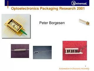
Optoelectronics Packaging Research 2001
Optoelectronics Packaging Research 2001. Peter Borgesen. Optoelectronics Packaging Research. Long term: Contribute to transition from low volume, partially manual and robot based assembly of ‘pieces’ to fully automated manufacturing like microelectronics. Requires combination of:

Optoelectronics Packaging Research 2001
E N D
Presentation Transcript
Optoelectronics Packaging Research 2001 Peter Borgesen
Optoelectronics Packaging Research Long term: Contribute to transition from low volume, partially manual and robot based assembly of ‘pieces’ to fully automated manufacturing like microelectronics. Requires combination of: design for manufacturing & quality materials development & characterization systems & equipment development process development Obviously won’t (can’t) do all this, but to contribute we must understand: Research and education.
Research & Education Research: Establish activities in ‘1st-3rd‘ level packaging Understand current practices Problem solving with/for manufacturers Research topics of generic, long term relevance to automated manufacturing Education: Relevant research experience for our students Work with university on manufacturing relevant curriculum 4 hour tutorial on basics of optoelectronics packaging
1st-3rd Level Packaging Optical Sub Assembly (OSA): Rotator, polarizer, birefringent crystals Laser attach Component assembly: TEC attach OSA attach Fiber: Handling & Reliability Pigtailing & Connectorization Component attachment: Adhesive Selective soldering?
Quality & Yields Initial impressions: Interesting combinations of high precision (active alignment) and manual or semi-manual assembly common. Reproducibility: Only know quality of part tested? Yields?
Coaxial Laser Module Aspherical lens Lens holder Welding ring Isolator Sleeve 5.6mm SM Fiber Laser 22mm Not exactly designed for manufacturing Simultaneous active alignment along 6 axes: Lens holder in X, Y (for lens) and (isolator) Fiber sleeve X, Y, Z
Generic 10Gbps Laser Module lens monitor diode on ceramic modulator on ceramic filter laser on ceramic OSA AlN isolator SELFOC lens TEC lenses Nor is this one !
Laser Diode Packaging Not all packages are that complicated. In it’s simplest form a laser diode package has a laser shooting into fiber The rest is a matter of optimizing performance and (too rarely) ‘manufacturability’
Edge Emitting Laser 1-3 gold wire bonds to same electrode electrical contact to substrate
Edge Emitting Laser Attach wire bond lensed fiber laser solder Edge emitting laser attached to prototyping substrate with In solder, and lensed fiber with Ruby ring
Prototype Laser Diode Package Very similar looking product still offered commercially fiber sleeve laser submount TEC ceramic ‘optical bench’ Ruby ring butterfly package UV tack adhesive
Optimizing Performance lens monitor diode on ceramic modulator on ceramic Free space coupling to selfoc and fiber filter laser on ceramic OSA AlN isolator SELFOC lens TEC lenses Parts all help optimize, but we still have choices to make: Package details (sealing), order of assembly & alignment. Free space/waveguides/lensed fiber/SSC (alignm. budget)?
Coupling of Edge Emitting Laser Modes are not well matched: Different sizes/divergencies Optimized butt coupling to cleaved SM fiber offers only 9% efficiency
SM Laser - Fiber Coupling Mode Field Diameter (MFD): 1/e2 width, typically 15% larger than core Mode field mismatch loss (perfect alignment): Effects of misalignment also depend on mode field diameters and match!
Coupling of Edge Emitting Laser Greatly improved by insertion of lens(es), but at the expense of reduced alignment tolerances.
Optical Aligment Consider transverse misalignment (x,y) only. Then excess (butt-)coupling loss In a sense lens may be viewed as increasing MFDlaser,x/y at the fiber surface, reducing sensitivity to x/y there reducing MFDfiber at the laser surface, increasing sensitivity to x/y there Laser-lens alignment in x-y now less tolerant.
Optical Aligment Angular alignment tolerance clearly depends on transverse and longitudinal misalignment. If both the latter are zero, loss contribution varies with So, expansion of either mode increases sensitivity to angular misalignment at location in question
Lensed Fibers Kyocera Lensed fiber offers >90% coupling efficiency, but is very expensive and reduces alignment tolerance
Lenses Single aspheric lens may offer 55% coupling efficiency Combine with GRIN lens: >90% Expensive, 0.2m alignment GRIN: Parabolical variation in n(r), flat surfaces
Ball Lenses Ball lenses are clearly less effective than aspheric and, in particular, GRIN lenses. However, they are cheaper and easy to use
Optical Aligment Alignment of fiber and/or lens to within 0.1-0.2m often required for 85-95% SM coupling. About 50% often achievable with 1m. Fiber variations (diameter, core concentricity, cladding elliptricity) seem to prohibit passive alignment to better than 1m.
Spot Size Conversion Blumenthal, UCSB Spot-size converter (in/at waveguide, amplifier, coupler, ...) may improve coupling (mode matching). Laser spot conversion raises lateral & longitudinal alignment tolerances (reduces angular tolerances).
Optical Aligment Expanding 0.3m laser spot to 1-2m before emission may raise tolerances to more than 1m. 0 -2 -4 -6 -8 w. spot-size converter 1.4m Coupling Efficiency (dB) 0.75m Regular laser -3 -2 -1 0 1 2 3 Position (m) Fish et al., UCSB
Optimize/improve Manufacturability ‘Classical’ butterfly package design is not equally suitable to all coupling schemes: Fiber manipulation through hole in wall unnecessarily ackward
Generic 10Gbps Laser Module Sensitivity to warpage/creep depends on alignment/coupling scheme (often not considered in design). Real products may use adhesives or AuSn solder & welding. Overall assembly issues very sensitive to choice.
Optical Bench Structure in Cooling Silicon or ceramic bench: Always CTE mismatches Almost always warpage FEM: ‘Typical’ structures may warp 0.2-0.4m/oC Sensitive to adhesive properties, but always significant (Plastic) creep properties important.
Laser Diode Package Contents Typical components include laser, monitor, modulator, lens, isolator, pigtail, filter, detector, amplifier, cooler, driver chip Let’s consider optical isolators: ‘Optical diodes’
Reflections ‘External cavity’ may create extra modes in SM laser. -30dB (0.1%) reflection may destabilize laser
Polarization Sensitive Optical Isolator intensity Polarcor Polarcor Rotator polarization Faraday rotator: Non-reciprocal rotation of polarized light
Polarization Insensitive Isolator Also developing polarization insensitive isolator and circulator. Separate components, just keep adhesive from optical path. Current (manual) practice showed obvious manufacturing issues: Quality/yields? Automatability?
Polarization Insensitive Optical Isolator Primary light transmission
Polarization Insensitive Optical Isolator GRIN lens GRIN lens Isolator Primary light focussed to minimum spot by GRIN lens. Exit beam focussed back into same fiber from 16m spread
Polarization Insensitive Optical Isolator Deflection of backward light: Divergent beams not focussed back into upstream fiber.
Polarization Insensitive Optical Isolator At a minimum optical path must be epoxy free adhesive 1mm View of interface between rotator and wedge Wedge/rotator/wedge sandwiches each glued together along edges. Minute gaps left by surface morphologies: Capillary action. Uncontrollable
Wideband Polarization Insensitive Isolator Optical isolator assembly with epoxy: Very small parts, awkward locations, lots of active alignment.
Wideband Polarization Insensitive Isolator coated fiber epoxy ferrule cylinder Pigtail prepared by inserting stripped into epoxy in ferrule. Ferrule epoxied into steel cylinder.
Wideband Polarization Insensitive Isolator AR coating epoxy GRIN GRIN lens epoxied into other end of steel cylinder
Wideband Polarization Insensitive Isolator cylinder fiber ferrule GRIN 8o magnet GRIN lens inserted into magnet and gap to cylinder filled with epoxy.
Wideband Polarization Insensitive Isolator magnet GRIN lens Another GRIN lens actively aligned with exit side
Wideband Polarization Insensitive Isolator Steel cylinder with GRIN lens and fiber ferrule (at other end) soldered to outside cylinder
Polarization Insensitive Optical Isolator GRIN lens GRIN lens Isolator Remember offset? But this manufacturer did not bother offsetting fiber opening at end of cylinder. End segment tilted, fiber bent to 1” radius. Uncontrolled! How well is stripped section protected from bending? (1/10 stripped fibers bent to 1” would last 11 days at 50%R.H.) 212m
Adhesives Adhesives offer some obvious attractions for automation. However, dispensing is a bit of an art form. Also, there are numerous issues with properties.
Adhesive Projects Importance of deposition process control: FEM Dipping, pin transfer and dispense of small volumes: Fundamentals and applied. Shifts in placement and cure: Effects of deposition control & materials properties (just started) Gap & constraint dependent cure kinetics & properties: Realistic configurations vs. DSC, DMA & data sheets Creep & misalignment: FEM & experiments (to come)
Adhesive Deposition Process Control Effect of temperature change on optical component with asymmetric adhesive fillets: Rotate 1o per oK !
Polarization Insensitive Optical Isolator Magnet opening w. isolator structure adhesive Small adhesive volumes in awkward locations
Adhesive Fixturing of TO-can Fiber TO-can Adhesive Small adhesive volumes in awkward locations, uniformity critical
Small Adhesive Volumes 0.25mm How small is small volume? This ball lens needs 1g of adhesive in small dot: wet-out important?
Flip Chip VCSEL by Dipping Au adhesive Alternative small volume application
Flip Chip VCSEL by Dipping Au adhesive Alternative small volume application