Download
1 / 26
320 likes | 581 Vues
A low-power delta-sigma modulator using dynamic-source-follower integrators. Ryoto Yaguchi, Fumiyuki Adachi, Waho Takao. Department of Information and Communication Sciences Sophia University. Outline. Introduction Background & Motivation Our Approach Proposed Integrator (DSFI)

E N D
A low-power delta-sigma modulatorusing dynamic-source-follower integrators Ryoto Yaguchi, Fumiyuki Adachi, Waho Takao Department of Information and Communication Sciences Sophia University
Outline • Introduction • Background & Motivation • Our Approach • Proposed Integrator (DSFI) • Output Sampling • Circuit Simulation • DS Modulators • 1st-Order DS Modulator • 2nd-Order DS Modulator • Performance Comparison • Conclusion
Outline • Introduction • Background & Motivation • Our Approach • Proposed Integrator (DSFI) • OutputSampling • Circuit Simulation • DSModulators • 1st-Order DSModulator • 2nd-Order DSModulator • Performance Comparison • Conclusion
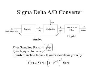
Background & Motivation Future communication applications need low power and high resolution ADCs. • SAR ADC • Low power operation • Limited resolution • DS ADC • High resolution • Higher power DSADC (Opamp) Resolution SAR ADC (Opamp-less) 1/Power
Approach DS Modulator Analog IN Digital Out Opamp-less Integrator Low Power DS Modulator We proposed a Dynamic Source Follower Integrator
Outline • Introduction • Background & Motivation • Our Approach • Proposed Integrator (DSFI) • OutputSampling • Circuit Simulation • DSModulators • 1st-Order DSModulator • 2nd-Order DSModulator • Performance Comparison • Conclusion 6
Dynamic Source-Follower Amplifier (MDAC) J. Hu, et al., JSSC ‘09 1.Sampling Phase Sampling Vin and Vref 2.Amplification Phase Redistributing charges
Proposed Integrator Previous work Dynamic Source-Follower Amplifier(MDAC) Dynamic Source-FollowerIntegrator Proposed Input Sampling 8
Proposed Integrator Previous work Dynamic Source-Follower Amplifier(MDAC) Dynamic Source-FollowerIntegrator Proposed Feedback path
Output Sampling C2a C2b Output Sampling Charge Redistributing Feedback path Feedback path Two capacitors for charge redistributing and output sampling,indepandently.
Simulation of DSFI Input Frequency = 20kHz Sampling Frequency = 0.5MHz Bode Plot 30 0.2 20 10 Gain [dB] 0 Input [V] 0 -10 0.1k 1k 10k 100k -0.2 Input Frequency[Hz] 1.0 0 Output [V] Phase [deg] -45 0 -90 -1.0 0.1k 1k 10k 100k 800 950 850 900 1000 Input Frequency[Hz] Time [ms] Successful integratoroperation
Outline • Introduction • Background & Motivation • Our Approach • Proposed Integrator (DSFI) • OutputSampling • Circuit Simulation • DSModulators • 1st-Order DSModulator • 2nd-Order DSModulator • Performance Comparison • Conclusion 13
1st-Order DS Modulator Vinp Voutp 0.3 Vinn Voutn Input [V] 0 Vdacp Vdacn -0.3 VDD Voutp 2 1 Vdacn Output [V] Vinp 0 Voutn 800 950 850 900 1000 Vdacp Time [ms] Vinn
1st-Order DS Modulator Spectrum 0 -20 -40 PSD[dB] -60 -80 20dB/dec -100 1k 1M 10k 100k 10M Frequency [Hz] 1st-order noise shaping characteristics are obtained!!
2nd DSFI 2nd-Order DS Modulator Charging Time Vinp 1st DSFI Charging capacitors before comparator decision Comparator decision Vinn Charging Redistribution To 1st DFSI Voutp To 1st DFSI Voutn
2nd-Order DS Modulator Spectrum 0 -20 -40 PSD[dB] -60 40dB/dec -80 -100 1k 1M 10k 100k 10M Frequency [Hz] 2nd-order noise shaping characteristics are obtained!!
Performance Comparison 2009 2009 2009 2009 2008 Proposed 0.18-mm, 2nd-order DS modulator has a good power efficiency comparable with those obtained by using 0.13-mm technologies.
Conclusion We proposed a dynamic source-follower integrator (DSFI), and applied it to opamp-less DS modulators. Operation of proposed 1st and 2nd order DS modulatorsdesigned by using a 0.18-mm CMOS technology successfully was confirmed by transistor-level circuit simulation. The designed 20-kHz BW, 73.8dB SNR, 2nd-order DS modulator has a good power efficiency comparable with those obtained by using 0.13-mm technologies.
CMRR at DSFI ・Output equation of typical differential amplifier: CMRR is very good!! ・CMRR: V++V-=0 V+-V-=0 Input p [V] Input p [V] Input n [V] Input n [V] Output [V] Output [V] Time [s] Time [s]
Clock Generators Q:For example, what about any digital circuits you needed to control switches? Non-overlap clock generator TFF-clock generator Input Input Output Output Time Time Generate φ2a,φ2b Generate φ1,φ2
DS modulator power consumption Q:In your power consumption estimation, what kinds of circuits are included? Others 0.5% Comparator 3.7% Clock Generators 7.1% 2nd DSFI 1st DSFI 47.1% 41.6% *)Without the referential voltage generators
Comparison Fairness Q: You compared your simulation results with the experimental results. Is this a fair comparison? We have to examine the comparison on experimental measurement, hereafter!! 2.5mm Clock Generator Comparator 2nd-order DSM 1st-DSFI 2nd-DSFI