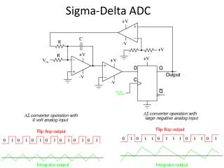
delta sigma modulator
Design and Simulation of multi mode Continuous Time -Delta Sigma Modulator for wireless communication standards

delta sigma modulator
E N D
Presentation Transcript
Sahand University of Technology Design and Simulation of multi mode Continuous Time -Delta Sigma Modulator for wireless communication standards • Advisor : • Dr. E. Najafiaghdam • Presented by : • Mohammad Honarparvar • M_honarparvar@sut.ac.ir
OUTLINE • Why ADCs • Types of ADC • Principles of ΔΣ modulator • Multi mode ΔΣ modulator • Simulations
WHY ADC ? Analog to Digital Converter 010110101
Types of ADC from the point of sampling frequency view ADCs • Delta based ADCs • Delta-Sigma based ADCs Nyquist - Rate ADCs Over sampling ADCs • Flash ADCs • Sub-Ranging ADCs • Folding ADCs • Pipelined ADCs • Successive Approximation (Algorithmic) ADCs • Integrating (serial) ADCs
Typical Nyquist - Rate ADCs ( FLASH ) Vin R/2 Vout - + R Flash ADCs R - - - - - • Advantage: • High speed • Disadvantages: • large area • high power dissipation • low-medium • resolution (6-10 bit) + + + + + Encoder R R R/2
Delta-Sigma idea Over Sampling Noise Shaping 1-bit quantizer ∑ / ∫ ∆ Advantages: very high resolution(12-24 bit) Analog part small area robustness to circuit imperfections Disadvantage : Moderate bandwidth due to oversampling Low speed - + 12-24 bit Resolution Wow !!!!!!!!!!!
Delta-Sigma Concepts : quantization noise ADC X(n) DAC Y1(n) e(n) Se(f) X(n) kx Quantization noise power density Y1(n) t -fs/2 -fs/2 f e(n) Δ/2 t -Δ/2
Delta-Sigma Concepts : over sampling Quantization noise and in-band noise for OSR = 1 Quantization noise and in-band noise for OSR = 4
Delta-Sigma Concepts : noise shaping Nyquist Rate Noise shaping Noise Level Over Sampling Frequency
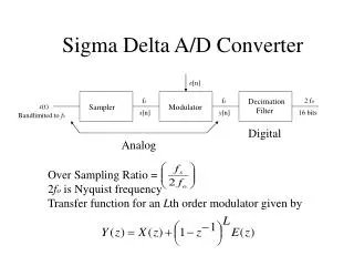
Delta-Sigma Concepts : DT and CT DT Δ Σ modulator CT Δ Σ modulator • Discrete Time • DSM Continuous Time AAF DSM Decimation DSM Decimation H(z) H(s) fs fs
Delta-Sigma Concepts : DT and CT STF : Signal Transfer Function NTF : Noise Transfer Function • Higher-order modulators • Add more integrators • Stability is a major issue
Delta-Sigma Concepts : comparison between CT & DT Continuous Time Discrete Time • Higher sampling frequency possible • Attenuated (noise shaped) S/H errors • Implicit anti aliasing filter • Relaxed Op-Amp speed requirements • Reduced supply and ground noise impact • Less glitch sensitive • Less digital switching noise • Breadboard prototyping possible • Lower simulation time(circuit level) • low-power • Low sensitivity to clock jitter • Low sensitivity to excess loop delay • Low sensitivity to DAC waveform • Accurately defined integrator gainsand transfer functions • Highly linear SC integrator • Lower simulation time (high level) • Capacitive loads only • Compatible with VLSI CMOS processes
Delta-Sigma Concepts : DSM structures ADC ADC DAC DAC
Delta-Sigma Concepts : DSM structures • Advantages : • The output swing of the first stage in the FF loop filter is much smaller than that of the FB counterpart • the number of feedback DACs in the FF architecture is much less than that in the FB counterpart in a high-order loop filter • drawbacks : • out-of-band peaking in the STF, which reduces the DR of the modulator • big adder is needed to sum all feed-forward
DSM structures : Multi Loop E1(z) • Multi Stage Noise Shaping (MASH) • Advantage : • Guaranteed stability • High over load level • Large SNR for Low OSR • Disadvantage : • Sensitivity to circuit imperfection • Lager complexity of the digital part • Mismatching between analog • parameter and digital estimation • parameter 2nd order DSM 2nd order DSM X(z) g Y2(z) Y1(z) H1(z) H1(z) Y(z)
Verifying the performance of system • Investigating the circuit • non-idealities effect • Optimizing the system parameters • Establishing the specifications for • the analog cells Design Flow System Level Device Level • Circuit simulation • Layout • Post layout • Market System-level simulation is a great benefit before circuit-level simulation
Problem Formulation • Building blocks of CT ∆∑M • Operational transconductance amplifiers • Operational amplifiers • Comparator • Current feedback blocks • Performance of ∆∑M is dependent on the nonidealities of the components
Addressed Non-Idealities • Clock jitter at the comparator • Operational amplifier noise • Integrator leakage due to finite gain • Amplifier finite bandwidth (BW) • Amplifier slew rate (SR) • Amplifier saturation • Transconductor nonlinearity
Clock jitter at the comparator • Temporal variation of clock period • Results in non-uniform sampling • Zero mean random variable
Ideal Integrator leakage due to finite gain Practical • Not infinite due to circuit constraints • Causes leaky integration • Modeled by subtracting a fraction of the integrator output from • the integrator input Ideal Practical Critical op-amp DC gain
Slew Rate and Finite Bandwidth • Slew rate affects nonlinear settling time • Finite BW affects linear setting time Critical op-amp BW 350 MHz Critical op-amp Slew Rate 340 V/us
Scaling of DSM coefficients Problems Solution • saturation of integrators in real implementations • Saturation of quantizer Before scaling After scaling Scaling coefficients of the Delta Sigma Modulator Out put of second int. Quantizer input Out put of first int.
Europe : GSM900 / DCS1800 / UMTS WCDMA 3G United-States : IS-95 / CDMA2000 China : TD-SCDMA Gabon : GSM900 Standards evolution on mobile terminals 1G AMPS NMT • Each area has its own • mobile standards • Broadband standards • Wi-Fi, IEEE802.11 • Cordless systems • DECT • Short-range systems • Bluetooth 2G EDGE GPRS GSM Wi-MAX WLAN Wi-Fi 4G Next Generation
Power consumption Chip area restrictions Why multi-standard ???? Base band RF band Multi standard solution Multi standard receiver
GSM WLAN Worldwide Communications Systems Bi-standard or tri-standard mobile phones VOICESMSDATAVIDEO… Single chip WCDMA Design of a reconfigurable RF transmitter IC able to address every standard • Large area needed and high power consumption • No reconfigurability • High manufacturing cost
Different wireless standards and some basic characteristics Quality of Service (QoS)
Why Delta Sigma ??? • these converters are able to trade efficiently speed for accuracy • low power dissipation • noise shaping and oversampling characteristics • high resolution over a wide variety of bandwidth requirements • high resolution with low precision components lies on the use of • over-sampling and noise shaping • Superior linearity • inherent bandwidth resolution tradeoff in the noise-shaping • characteristic • robustness to circuit imperfections • increased programmability in digital domain • lower the specifications for the anti-aliasing filter ( CT )
Parallel Global (worst case) Flexible / Reconfigurable Design approach
Parallel Design approach GSM WCDMA WLAN Baseband signal processor GSM mode DSM 0.2 MHz WCDMA mode DSM WLAN mode DSM 2 MHz 20 MHz • most straightforward way • may be power efficient • chip area • cost
Global Design approach worst-case set of specifications ( WLAN) Very inefficient Consume way too much power for most of the standards and operation modes
Flexible / Reconfigurable Design approach 0.2 MHz GSM WLAN Flexible / Reconfigurable WCDMA • O.K. 2 MHz 20 MHz
SYSTEM ARCHITECTURE Golden key DR : Dynamic range L : Order of modulator OSR : Over Sampling Ratio B : Quantizer Resolution fs : Sampling Frequency f0 : Modulator Bandwidth
SYSTEM ARCHITECTURE : Drawbacks and Suggestion Increasing the order of the modulator Increasing the resolution of the quantizer Increasing the Sampling frequency Drawbacks Suggestion Drawbacks Suggestion Drawbacks Suggestion Stability concerns higher order digital filter downstream • L=3 and L=4 are optimal for multi standard wireless application because they • can offer satisfied resolution and bandwidth for different standards with • reasonable sampling frequency power dissipation circuit area feedback DAC DEM technique considerable complexity to the design • already the best way power in the quantizer and feedback DAC process limitations in 0.18μm 500MHz is reasonable • Sampling frequency is selected as a multiple of the chip or symbol rate of the wireless modulation standard
Simulations A Multi-Mode Sigma-Delta ADC for GSM / WCDMA / WLAN Applications [Babita R. Jose] GSM mode WCDMA mode GSM mode WLAN mode WCDMA mode WLAN mode
Simulations A 1.2-V Dual-Mode WCDMA/GPRS ΣΔ Modulator [Alessandro Dezzani]
Simulations A Triple-Mode Sigma-Delta Modulator for Multi-Standard Wireless Radio Receivers [ANA RUSU] GSM mode WCDMA mode WLAN mode
GSM 0.2 MHz
WCDMA 2 MHz
WLAN 20 MHz
Conclusion • Multi standard communication systems • Power consumption • Chip area considerations • Base band part • Delta sigma modulator • Continuous time DSMs
References L. Xiaopeng, M. Ismail, Multi-standard CMOS wireless receivers : analysis and design, Kluwer academic publishers, 2002. 0-306-47309-7. B. R. Jose, J. Mathew, and P. Mythili, “A multi-mode Sigma-Delta ADC for GSM/WCDMA/WLAN applications,” Journal of Signal Processing Systems, Springer Science + BusinessMedia,2008. A.Rusa, A. Borodenkov,M. Ismail, and H.Tenhunev “A triple-mode Sigma-Delta modulator for multi-standard wireless radio receivers,” Analog Integrated Circuits and Signal Processing, Springer Science + Business Media, vol. 47, pp. 113–124, 2006. A.Rusa, D. R. González , and M. Ismail, “Reconfigurable ADCs enable smart radios for 4G wireless connectivity,” IEEE Circuits and Devices Magazine, vol. 22, pp. 6–11, May-June 2006. 8755-3996. M. Ortman, and F.Gefers, Continuous-time Sigma-Delta A/D conversion; fundamentals, performance limits and robust implementations,Springer, 2006. 1437-0387. E.N.Aghdam, P. Benabes, J. abbasszadeh “ Completely First Order and Tone Free Part it ioned Data Weighted Averaging Technique Used in a Multibit Delta Sigma Modulator ", European Conference on Circuit Theory and Design, , ECCTD 2009 . J. Silva, U. Moon, J. steensgaard, and G. C. Temes, “Wideband low-distortion delta-sigma ADC topology,” Electronics Letters, vol. 37, pp. 737–738,Jun 2001. 0013-5194. Y. Wang, and G. C. Temes, “Noise-coupled continuous-time delta-sigma ADCs,” Electronics Letters, vol. 45, March 2009. E. C. Fréchette, and G. Gagnon, “A new optimization technique for coefficient scaling in sigma-delta modulators,” Seattle, WA , pp. 312–315, 2010. 1548-3746. G. Gomez, and B. Haroun,“ A 1.5V 2.4/2.9mW 79/50 dB DR ΣΔ Modulator for GSM/WCDMA in a 0.13μm Digital Process,” In IEEE ISSCC Conference Digest of Technical Papers, pp. 242–244, 2002.