Understanding Traffic Sign Logic Control and State Machine Data Paths in Computing
This document explores the functionality of a blinking traffic sign system and its logic control using state machines. It details the various states that can be reached depending on the switch input and the corresponding outputs, represented through truth tables. The explanation covers essential components in combinational and sequential logic, including controllers, data paths, decoders, multiplexers, and ALUs. This foundational knowledge is crucial for understanding how data is processed in computing systems, specifically contrasting logic paths and control signals for efficient operation.

Understanding Traffic Sign Logic Control and State Machine Data Paths in Computing
E N D
Presentation Transcript
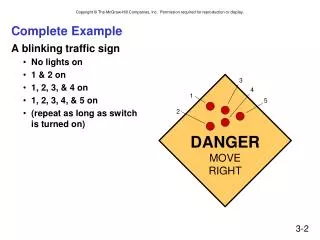
Complete Example • A blinking traffic sign • No lights on • 1 & 2 on • 1, 2, 3, & 4 on • 1, 2, 3, 4, & 5 on • (repeat as long as switchis turned on) 3 4 1 5 2 DANGERMOVERIGHT
Traffic Sign State Diagram Switch on Switch off State bit S1 State bit S0 Outputs Transition on each clock cycle.
Traffic Sign Truth Tables Outputs (depend only on state: S1S0) Next State: S1’S0’(depend on state and input) Switch Lights 1 and 2 Lights 3 and 4 Light 5 Whenever In=0, next state is 00.
Traffic Sign Logic Master-slaveflipflop
Controller + Data Path • Sometimes there are lots and lots of states, but a fairly simple way to move between states. • We can separate the data being transformedfrom the state machine that's controlling the transform. State Machine Combinational Logic Circuit Storage Elements Controller + Data Path
From Logic to Computer Data Path • The data path of a computer is all the logic used toprocess information. • See the data path of the LC-3 on next slide. • Combinational Logic • Decoders -- convert instructions into control signals, access memory • Multiplexers – select inputs and outputs • ALU (Arithmetic and Logic Unit) – performs operations on data • Sequential Logic • State machine -- coordinate control signals and data movement • Registers and latches -- storage elements