Download
1 / 27
270 likes | 404 Vues
EFI Operation and First Results J. W. Bonnell With many thanks to: F. Mozer, J. McFadden, C. Cully the THEMIS Engineering, Science, Mission Ops and SciSoft Teams. Outline. Milestones Operational Modes DC and AC Performance On-Orbit Deployed State and Bias Settings Systematic Errors

E N D
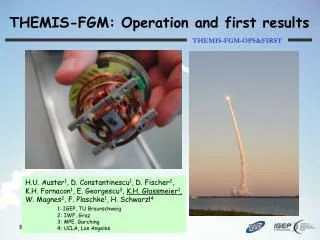
EFI Operation and First Results • J. W. Bonnell • With many thanks to: • F. Mozer, J. McFadden, C. Cully • the THEMIS Engineering, Science, Mission Ops and SciSoft Teams
Outline • Milestones • Operational Modes • DC and AC Performance On-Orbit • Deployed State and Bias Settings • Systematic Errors • Cold Plasma Wakes • 20 July 2007 -- Hall fields at the M’Pause. • AC Performance • L1 and L2 Data and Data Analysis Support • Near-Term Efforts
EFI Wants YOU! Coloumb Faraday Franklin Tesla We want YOU to join the EFI Team – • Travel to the far reaches of the terrestrial magnetosphere in search of E-fields! • Painstakingly detect and calibrate away significant systematic errors! • Measure quasi-DC fields associated with large-scale plasma physics at various magnetospheric boundaries! • Make quantitative measurements of the waves in wave-particle interactions! The Few – the Proud – THEMIS EFI
Operational Modes - EFI • Continuous coverage of lower-rate data through burst periods. • Slow Survey (time-tag commanded): • Filter Bank (2 channels (SCM1, EAC12), 6 frequencies + AKR, 1 spec/4 s). • Spin Fit V, E, and B. • NEW, since early July! Waveform V (6 channels, 4 samp/s) • NEW, since early July! Waveform E (3 channels, 4 samp/s) • Fast Survey (time-tag commanded) • Waveform V (6 channels, 4 samp/s). • Waveform E (3 channels, 8 samp/s). • Particle Burst (time-tag commanded; to be on-board triggered) • Waveform V (6 channels, 16 samp/s). • Waveform E (3 channels, 128 samp/s). • FFT Spectra (4 channels, 16 freq. bins, 4 spec/s; may be reassigned to SS). • Wave Burst (time-tag commanded; to be on-board triggered) • Waveform V (6 channels, 8192 samp/s). • Waveform E (3 channels, 8192 samp/s). • FFT Spectra (4 channels, 16 freq. bins, 4 spec/s).
Calibration - EFI • Ground Electrical and mechanical calibrations completed in Oct ’05. • Results of In-Flight calibrations will be fed back into revised L1 CAL procs and data, and will be used in the production of L2 physical quantities: • Intercomparison between Vptcl and ExB -> Leff. • Intercalibration between Vsc and particle density -> n(Vsc). • Estimation of offsets due to differential photemission (sphere vs. sphere; the sunward E-field offset, etc.). • Optimization and estimation of sensor coupling parameters. • Deployed Boom Lengths (TH-C, D, and E): • X-axis (V1-V2), 49.6 m, sphere center-to-center. • Y-axis (V3-V4), 40.4 m, sphere center-to-center. • Z-axis (V5-V6), 5.63 m, whip center-to-center, 6.39 m tip-to-tip, whips are 0.76-m long each.
Bias Settings, Other Caveats • Last set of Sensor Diagnostic Tests run on TH-C, D, and E over two orbits, 30 June – 2 July 2007 (3 runs/orbit/probe). • Last BIAS table updates -- 20 July 2007: • BIAS set to ~-175 nA/sensor (factor of ~2 increase in photoemission over <2 months; typical). • USHER and GUARD set to positive voltage. • DBRAID driven by V1. • Other Caveats: • One-sec timing glitches. • Occur on many data types. • Occur when IDPU processor is running heavy oreground tasks (e.g. compression during SlowSurvey just after exit from FastSurvey). • Can cause sudden 120-deg shifts in despun data. • Recoverable in L0->L1 processing (to be implemented soon).
Waveform EFI Data • Waveform data similar between TH-C, D, E. • Data are available at full set of rates (FS, PB, and WB). • SC potential and ES wake effects more significant than on previous magnetospheric missions (Cluster, Polar).
Spin Plane vs. Spin Axis E • Spin-plane E-field estimates are reasonable given past observations. • Spin-axis E-field estimates show significant common-mode (SC potential) effects.
Axial E vs. Vsc • Significant correlation between v56 (axial E-field) and Vsc (avg(v1, v2)) over a broad range of spacecraft potentials (ambient densities). • Correlation is not strictly linear, and breakpoints probably represent changes in photocloud structure with SC potential.
Vsc vs. Ambient Density • Typical two-slope correlation between Vsc and ambient ion density estimate (ESA). • Population of points below curve probably represent presence of cold plasma, e.g. Scudder et al., [2000] result for Polar.
Estimating Offsets and Eff. Boom Lengths Solar Wind, 30 June 2007 Magnetosheath, 30 June 2007
Estimating Offsets and Eff. Boom Lengths When not affected by ES wake effects: • Sunward offsets are 1-2 mV/m (~Cluster and Polar). • Effective Boom Lengths are a factor of 1.5 to 1.7 times smaller than Physical Boom Length (significantly different than Cluster+Polar (~1.2 to 1.5), and predictions (~1.05 to 1.1 for vacuum)). • Correlation studies between EFI, ESA, and FGM to compare E with –VixB suggest that FGM spin axis offset can differ from calibrated value; ie. Best long-term fit between E and –VixB uses Bz offset different than std. FGM value (McFadden).
ES Cold Plasma Wake • Waveforms non-sinusoidal. • Shorter boom pair (v34) has LARGER signal than long boom pair (v12). • Distortion reminiscent of cold plasma wake effect on Cluster [eg. Engwall et al., 2006] Figures courtesy C. Cully.
Optimal DC Performance … When it all works right …
L1 and CAL, Analysis - EFI • L1 CDF files for each collected data type (FilterBank, SpinFit, FS Vs, PB Es, etc.). • L1 CAL procs and data currently account for Ground calibrations and deployed boom lengths. • Revised calibrations (offsets, effective boom lengths, etc.) based on in-flight testing will be included in subsequent releases. • Results to be produced in Despun Spacecraft (DSL) coordinates: • Standard spin-independent and -dependent offset estimation and removal will occur in intermediate coordinate systems (Probe Geometric, Spinning Spacecraft). • Options to enforce E dot B = 0, Eaxial = 0 will be included. • Data analysis based on exiting IDL TPLOT package and modified FAST fields processing routines (auto- and cross-spectra, etc.). • NEW !!! Old-School SDT-based data analysis fully-supported.
Physical Qtys, L2 Data - EFI • Spacecraft potential and density proxy (spin resolution or better). • Waveform sensor potentials (V-channels) and 3-axis E-field estimates (E-channels); resolution as shown in Operational Modes. • Spin Fit E fields (spin-resolution). • Spectral Data Products: • Filter Banks (0-4 kHz + AKR). • PB and WB FFT spectra • Individual channels or on-board para/perp Derived Quantities. • Proposed L2 data quantities (spin-period resolution): • AKR power. • SC potential or derived density. • 3-axis E-field (E dot B=0, with Eaxial=0). • 0-4 kHz EFI spectrum (1 axis, derived from FilterBank).
Near-term Efforts • Implementation and tuning of Derived Quantities spectra. • Evaluation of full-orbit FFT spectra support. • Preparation for boom deploys on final two probes. • Continued EFI/ESA/FGM inter-calibration efforts (E-field). • Determination of nominal offsets and effective antenna lengths. • ESA/EFI inter-calibration for n(Vsc). • Sub-spin-period density estimates. • Cold plasma detection. • Initial work on axial DC calibrations.
Modeling of Potential Distribution All figures, courtesy C. Cully.
Hall Fields, 20 July 2007 (3) Discussion of first figure. 1. Shows comparison of E and –vXB during period of magnetopause xngs. 2. Can see the magnetopause in B (2nd from bottom) or density (3rd from bottom) 3. Comparison of E and –vxB in 3rd and 4th panels from top. Red is E 4. Many regions of agreement and disagreement. Disagree when ion density not equal to electron density (4rd from bottom) due to cold ions not measured 5. Disagreements of E and –vxB occur due to cold plasma wake. 6. EXCEPT FOR 1033 WHEN THERE IS NO COLD PLASMA WAKE. THIS IS VERY LIKELY DUE TO HALL TERM (jxB/ne) IN REGION CARRYING MAGNETOPAUSE CURRENT!
Hall Fields, 20 July 2007 (4) Discussion of 2nd figure • Event on 20 July 2007 at magnetopause crossing seen in B (bottom panel) or density (SC potential in 4th panel from bottom) • EX disagrees with (-vxB)x at the current layer. Discussion of 3rd figure. This figure plots EX, (-vxB)x and [(jxB/ne)x – (vxB)x] EX disagrees with –(vxB)x but agrees with [(jxB/ne)x – (vxB)x] Reason is E +vxB = jxB/ne + small terms So this is a direct observation of the Hall E-field, potentially in a reconnection layer. NOTE THAT THERE IS NO QUADRUPOLAR BY signature here.