Download

1 / 23
230 likes | 353 Vues
The Design of Beam Profile Monitor and the test at SRRC. Chien-Wen Chen. For the FLASH Collaboration by Taiwan CosPA Members W-Y.Pauchy Hwang, Guey-Lin Lin, Ming-Heuy Huang, Chien-Wen Chen, Feng-Yin Chang,

E N D
The Design of Beam Profile Monitor and the test at SRRC Chien-Wen Chen For the FLASH Collaboration by Taiwan CosPA Members W-Y.Pauchy Hwang, Guey-Lin Lin, Ming-Heuy Huang, Chien-Wen Chen, Feng-Yin Chang, Chih-Ching Chen, Yu-Chung Chen, Staff Member :Maggie Wang
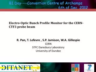
DESIGN OF BEAM PROFILE MONITOR TITANIUMFOIL ELECTRON BEAM TUNNEL CONTROLROOM WINDOWS XP WINDOWS XP @ @ LAN PC1 PC2 CAMERA (WORKSTATION) (LAPTOP) TRANSFER DATA OF & POSITION SLAC TRIGGER SYSTEM CAMERA CONTROL, IMAGE DOWNLOAD, DATA ANALYSE MONITORING, REMOTE CONTROL HUMAN
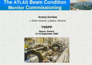
titanic foil object distance 35cm 29cm total 64cm lens six way cube tube CCD IEEE 1394 beam pipe Trigger circuit beam axis
1.3cm 8cm (outer) screw holes 7cm (inner)
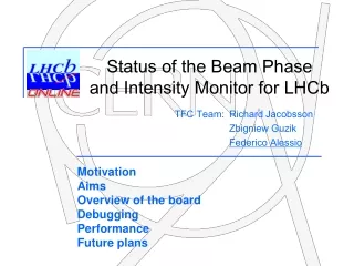
Top view – not to scale 6 inch beam pipe e- 2 ft Cable tray/Wall OTR “cube” optical table 2 ft Beam line flange. 28 inches (wall-to-beam-axis) 25 inches (wall-to-wall) ~ 63.5 cm
3x3 binning Spot 340 200 ROI 200 Full Frame 440
OTR efficiency and angular distribution of a single electron for a metal foil: transmission efficiency OTR efficiency quantum efficiency pixels # of electrons distribution readout noise dark current
The Algorithm Integrating over one axis 200 < x > 200 200
Signals per Pixel In SLAC 30GeV 10^8 e/bunch photoelectron Maximum intensity can be analysed :1.05x10^9 e/bunch pixel Plotted by Feng-Yin
Signal (Integrating over One Axis) In SLAC 30GeV 10^8 e/bunch photoelectron pixel
Signal to Noise Ratio per Pixel Center(93) In SLAC 30GeV 10^8 e/bunch photoelectron pixel
Signal to Noise Ratio (Integrating over One Axis) In SLAC 30GeV 10^8 e/bunch photoelectron pixel
trigger exposure readout download the image analyse transfer download the analysed data 360GB / 80KB = 4.5x10^6 (events)
aluminum coating mirror stainless window beam pipe
Data captured in SRRC 1.5 GeV σx=1.22 mm photoelectron pixel Signals = 450457 photoelectrons
Theoretical calculation in SRRC 1.5 GeV e/bunch σx=1.22 mm photoelectron Total photoelectrons =256389 pixel
photoelectron Experimental : 450457 photoelectrons 450457 / 256389 = 1.757 (two metal surface) Factors which may had made the difference: twice OTR, instability of the current, interference of the twice OTR. Theoretical : 256389 photoelectrons (one metal surface)
Conclusions 1.We have captured and downloaded the image of OTR at SRRC. 2.The S/N ratio seems to be big enough, so that we may sacrifice some of it to increase the MAX intensity of events which can be analysed . 3. The code to analyse and transfer data is yet to be accomplished.